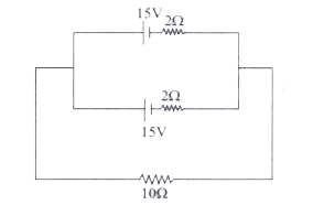
A circuit is shown in the figure.
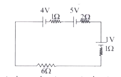
What is the total resistance in the circuit ?
5
6
11
30
The correct Answer is:C
Total resistance = Internal resistance + External resistance
=(1+2+1)Ω+6Ω
=11Ω
Topper's Solved these Questions
- SOURCES OF ELECTRIC CURRENTBook:CENGAGE PHYSICSChapter:SOURCES OF ELECTRIC CURRENTExercise:OLYMPIAD AND NTSE LEVEL EXERCISES
Explore 10 Videos
- SOURCES OF ELECTRIC CURRENTBook:CENGAGE PHYSICSChapter:SOURCES OF ELECTRIC CURRENTExercise:MANDATORY EXERCISE (Exercise Set IV)
Explore 9 Videos
- REFRACTION OF LIGHT Book:CENGAGE PHYSICSChapter:REFRACTION OF LIGHT Exercise:OLYMPIAD AND NSE LEVEL EXCERCISES
Explore 10 Videos
- STATIC ELECTRICITYBook:CENGAGE PHYSICSChapter:STATIC ELECTRICITYExercise:OLYMPIAD AND NTSE LEVEL EXERCISES
Explore 10 Videos
Similar Questions
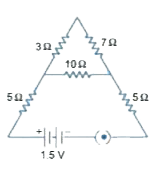
Five resistances are connected in the shape of letter A as shown in figure alongside. Determine the total resistance of the circuit.
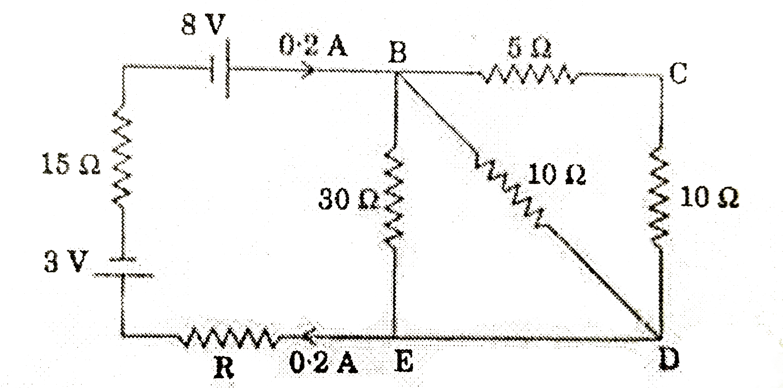
View SolutionCalculate the value of the resistance R in the circuit shown in the figure so that the current in the circuit is 0.2 A. What would be the potential difference between points B and E?
View Solution
Knowledge Check
Total resistance of the circuit:
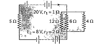 A10ΩB20ΩC5ΩD15Ω
In LCR circuit as shown in figure
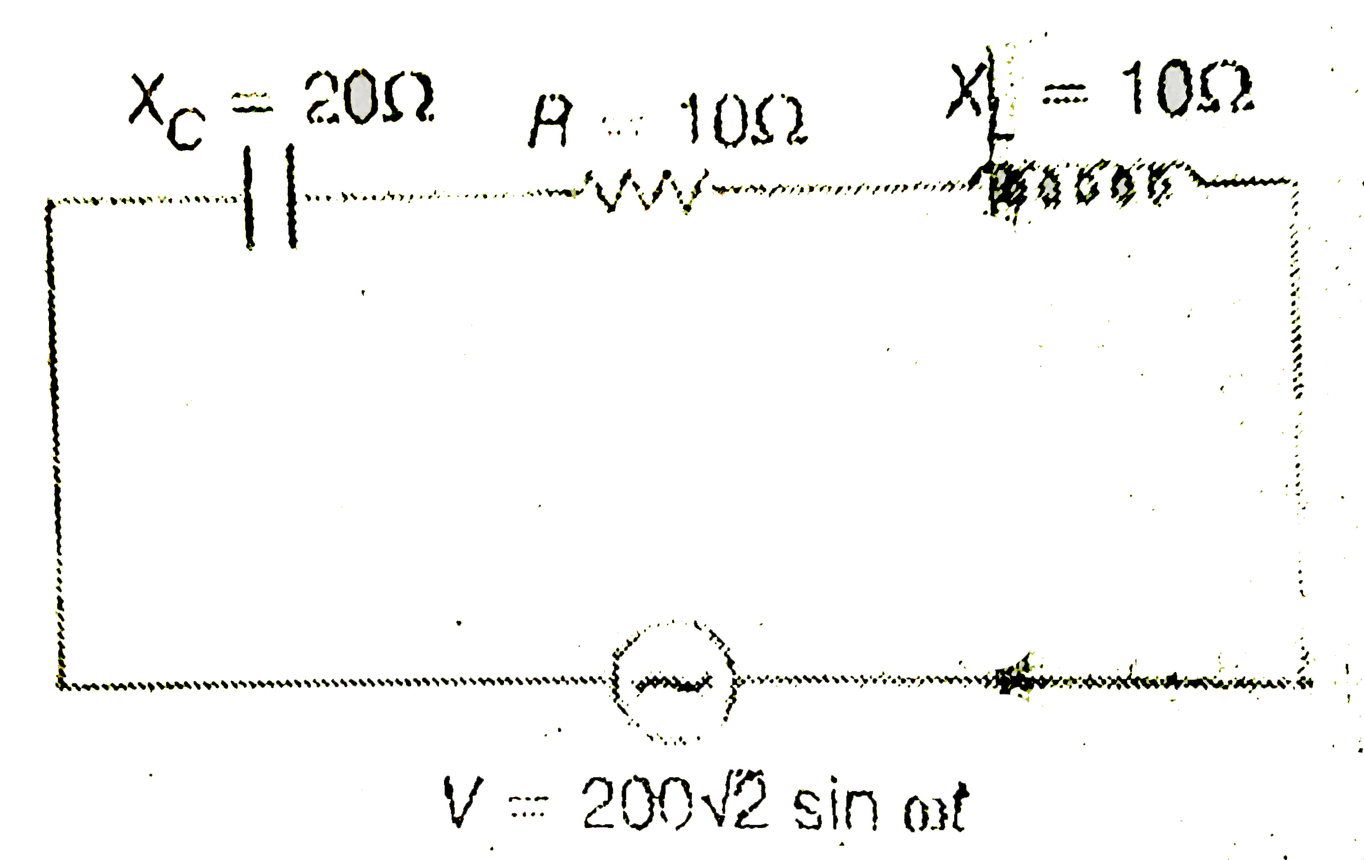 Acurrent will lead the voltageBrms value of current is 20ACpower factor of circuit is 1√2Dvoltage drop across resistance is 100V
The circuit shown in the figure acts as
 AOR gateBAND gateCNOT gateDNAND gate
The circuit as shown in the figure is equivalent to

View SolutionIn the circuit as shown in figure the
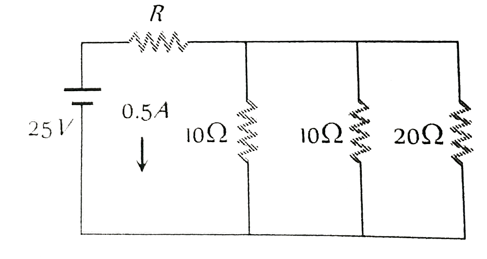
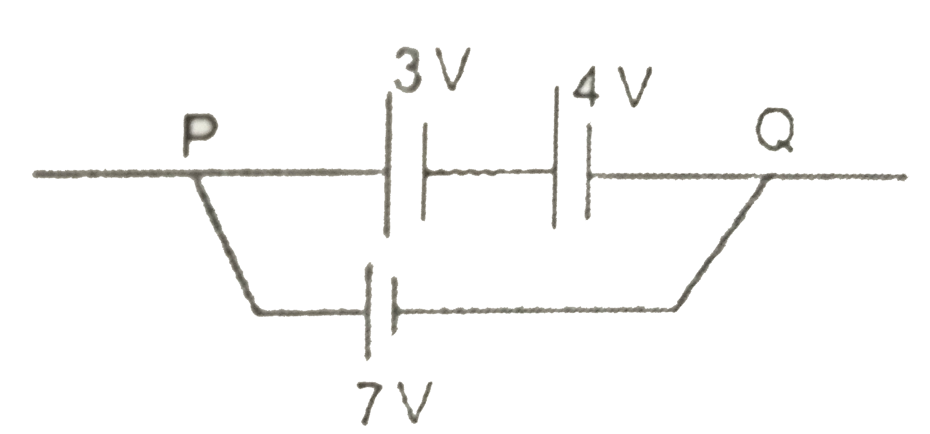
View SolutionThree batteries are connected as shown in the figure.
Then the total emf in the circuit is ____ V.
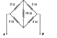
View SolutionWhat is the total resistance across A and B in the circuit shown in
View SolutionFor the circuit shown in the figure what is the potential difference across the external resistance ?
View Solution

