A resistor circuit is constructed such that 12 resistor are arranged to form a cube as shown in fig. Each resistor has a resistance of 2Ω. The potential difference of 30V is applied across two of the opposing points as shown
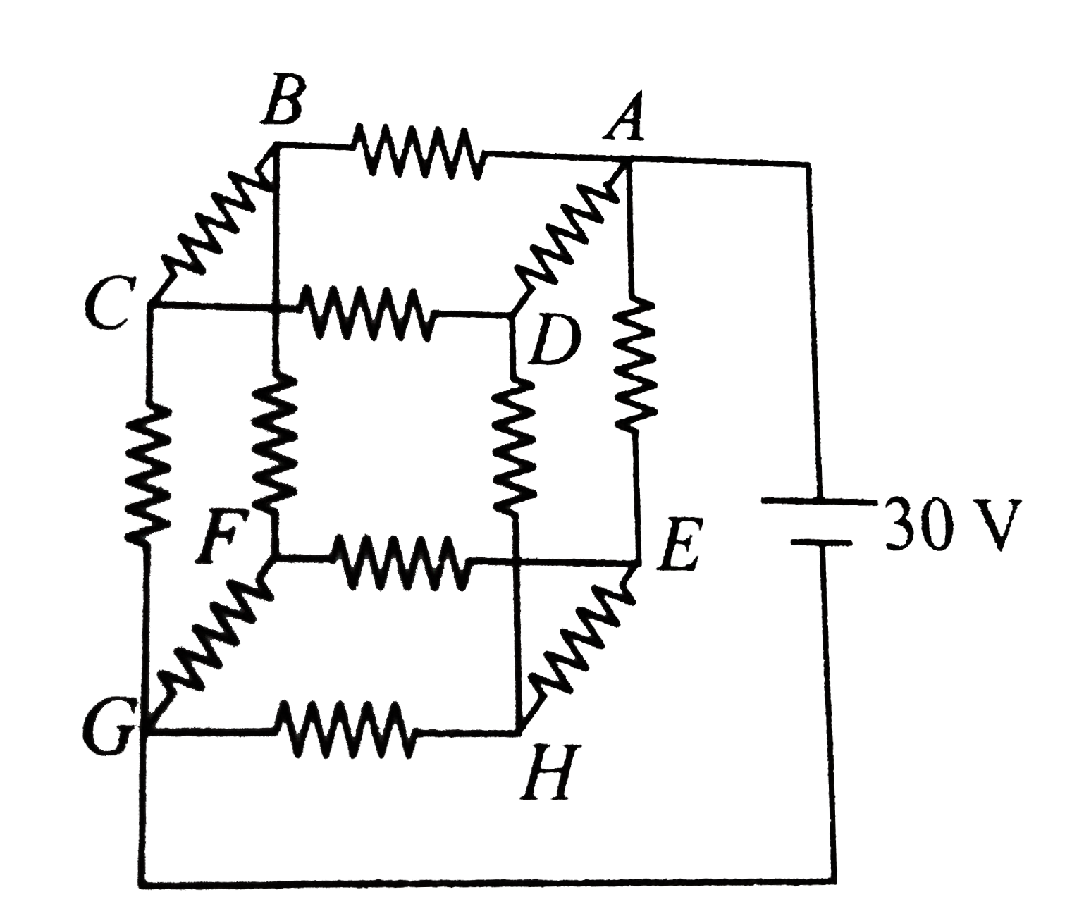
In question 20, the potential difference between the points C and G is
12V
10V
20V
7.5V
The correct Answer is:A
D, B, and E are are symetrical
to A, hence potential at these
points is same. Similarly , C,
F, and H are symmetrical
to G. So potential at these
points is the same.
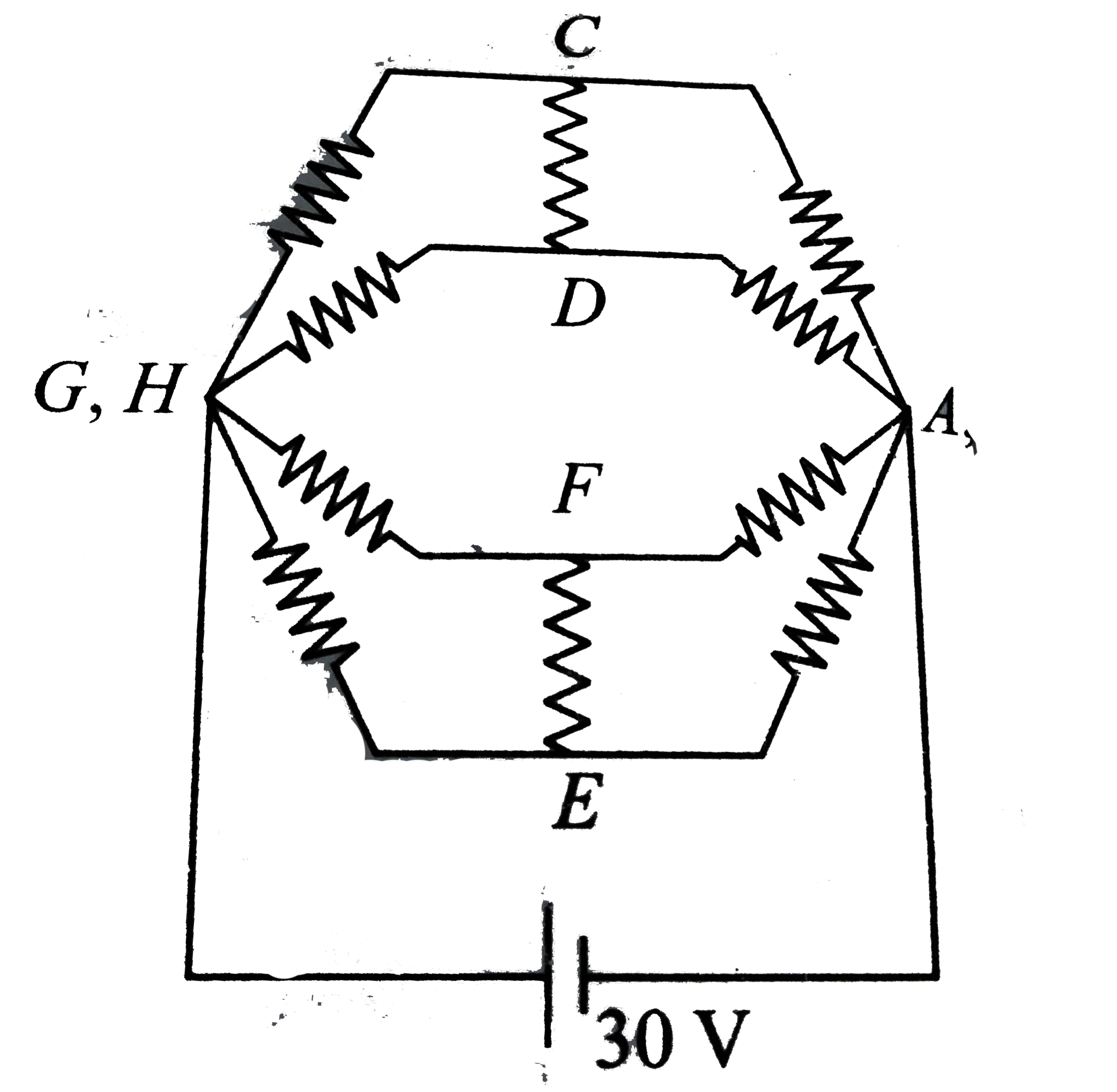
Resulting diagram will be
as shown : C, D, F, and E will
be at the same potential.
Potential difference between
C and G will be half to the applied potential, i.e.,
VCG=30/2=15V
Topper's Solved these Questions
- ELECTRIC CURRENT AND CIRCUITBOOK - CENGAGE PHYSICS ENGLISHCHAPTER - ELECTRIC CURRENT AND CIRCUITEXERCISE - Interger
8 Videos
- ELECTRIC CURRENT AND CIRCUITBOOK - CENGAGE PHYSICS ENGLISHCHAPTER - ELECTRIC CURRENT AND CIRCUITEXERCISE - Multiple Correct
16 Videos
- ELECTRIC CURRENT & CIRCUITSBOOK - CENGAGE PHYSICS ENGLISHCHAPTER - ELECTRIC CURRENT & CIRCUITSEXERCISE - Kirchhoff s law and simple circuits
15 Videos
- ELECTRIC FLUX AND GAUSS LAWBOOK - CENGAGE PHYSICS ENGLISHCHAPTER - ELECTRIC FLUX AND GAUSS LAWEXERCISE - MCQ s
38 Videos
Similar Questions
A resistor circuit is constructed such that 12 resistor are arranged to form a cube as shown in fig. Each resistor has a resistance of 2Ω. The potential difference of 30V is applied across two of the opposing points as shown
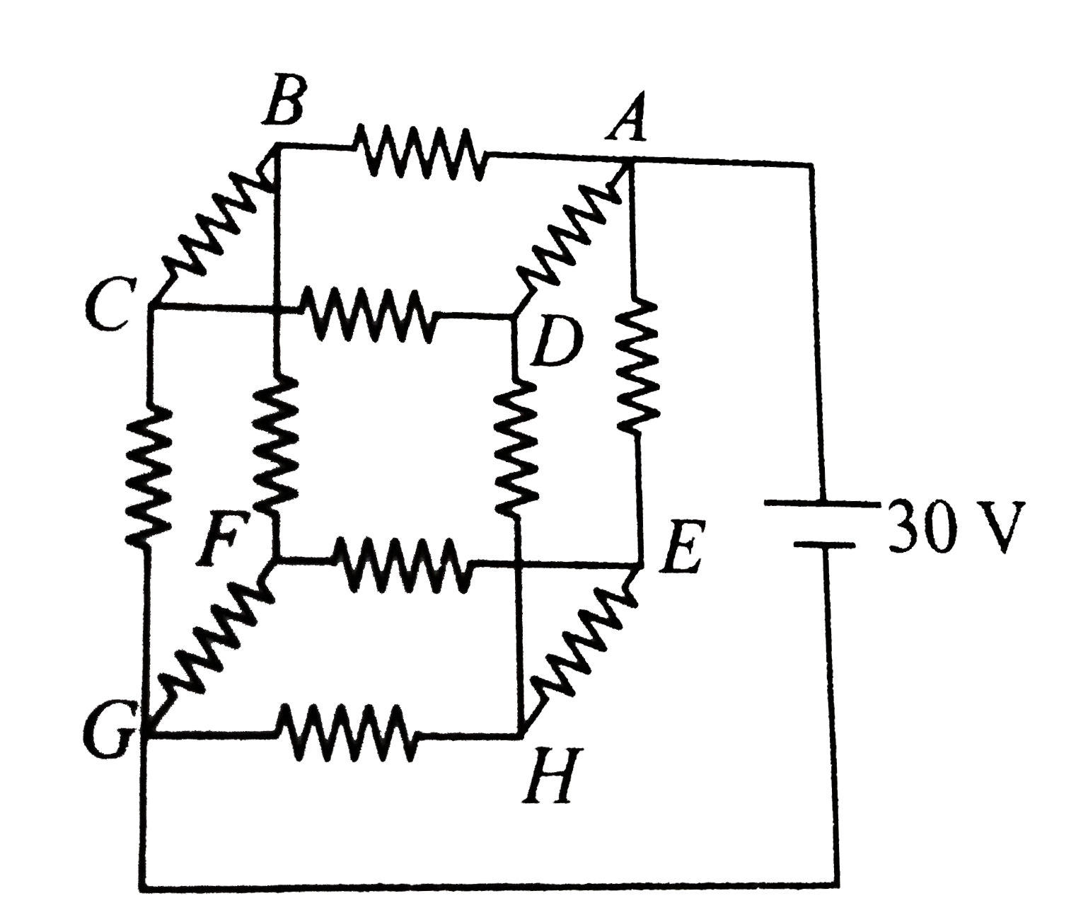
If we replace resistor between A and B and resistors between G and H by wires of zero resistance, then the points having the same potential are
i. D,E,C,F ,ii. A,B ,iii. G,H
View SolutionA resistor circuit is constructed such that 12 resistor are arranged to form a cube as shown in fig. Each resistor has a resistance of 2Ω. The potential difference of 30V is applied across two of the opposing points as shown
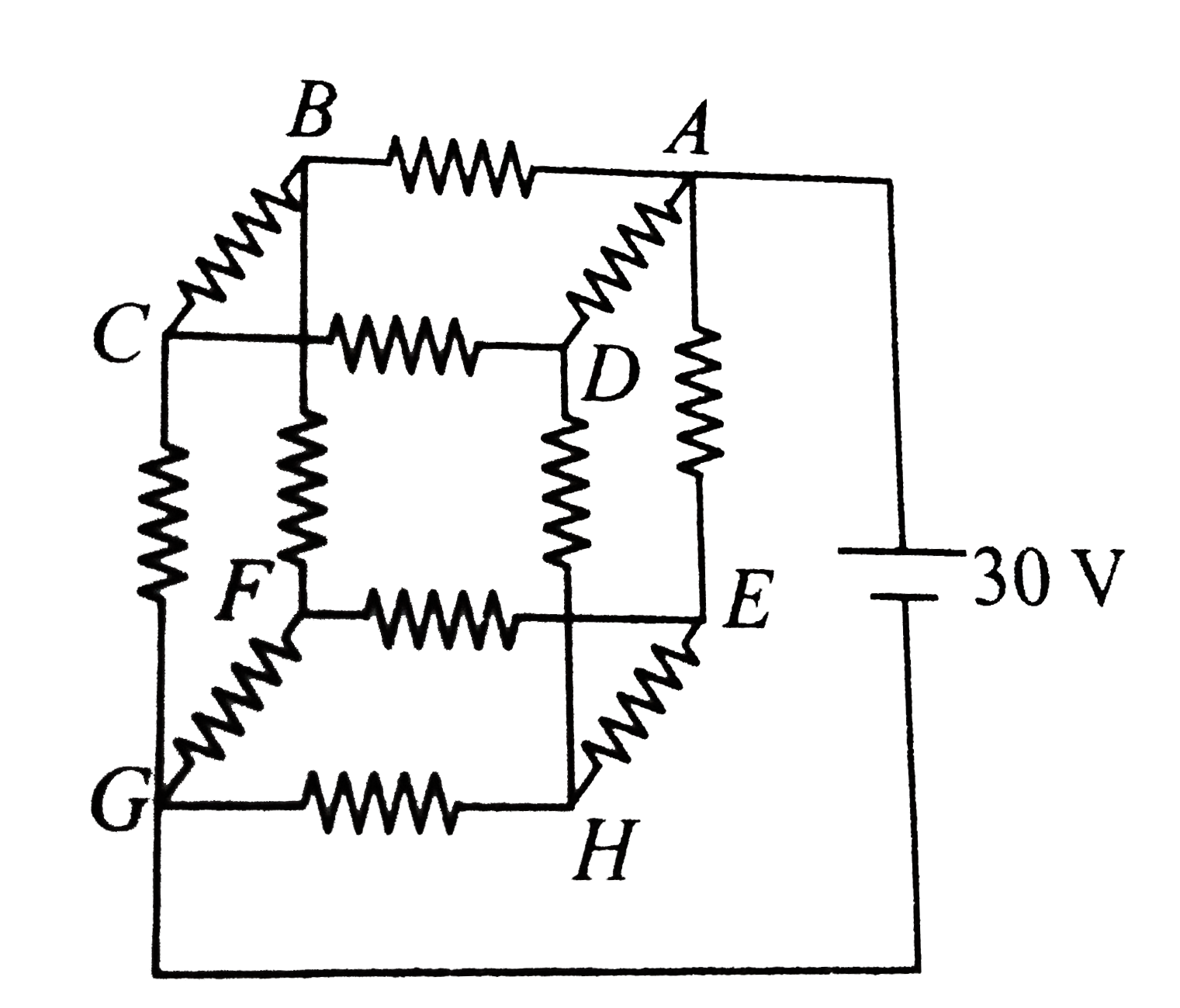
The points having the same potential are
i. B,D,E ,ii. C,F,H ,iii. C,E
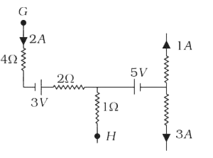
View SolutionIn the circuit shown, the potential difference between the points G and H, VG−VH is equal to _________ V.
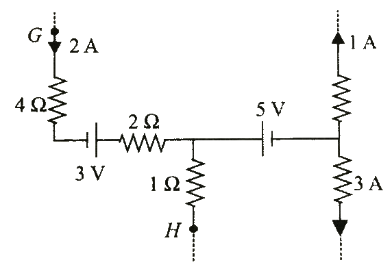
View SolutionIn the part of a circuit shown in fig. 5.266, the potential difference (VG−VH) between points G and H will be
View SolutionFor the combination of resistors shown in Fig. find the equivalent resistance between the points
C and D

View SolutionA resistor of 6 Ω is connected in series with another resistor of 4 Ω. A potential difference of 20 V is applied across the combination. Calculate :
the potential difference across the 6 Ω resistor.
View SolutionFor the combination of resistors shown in Fig. find the equivalent resistance between the points
A and B

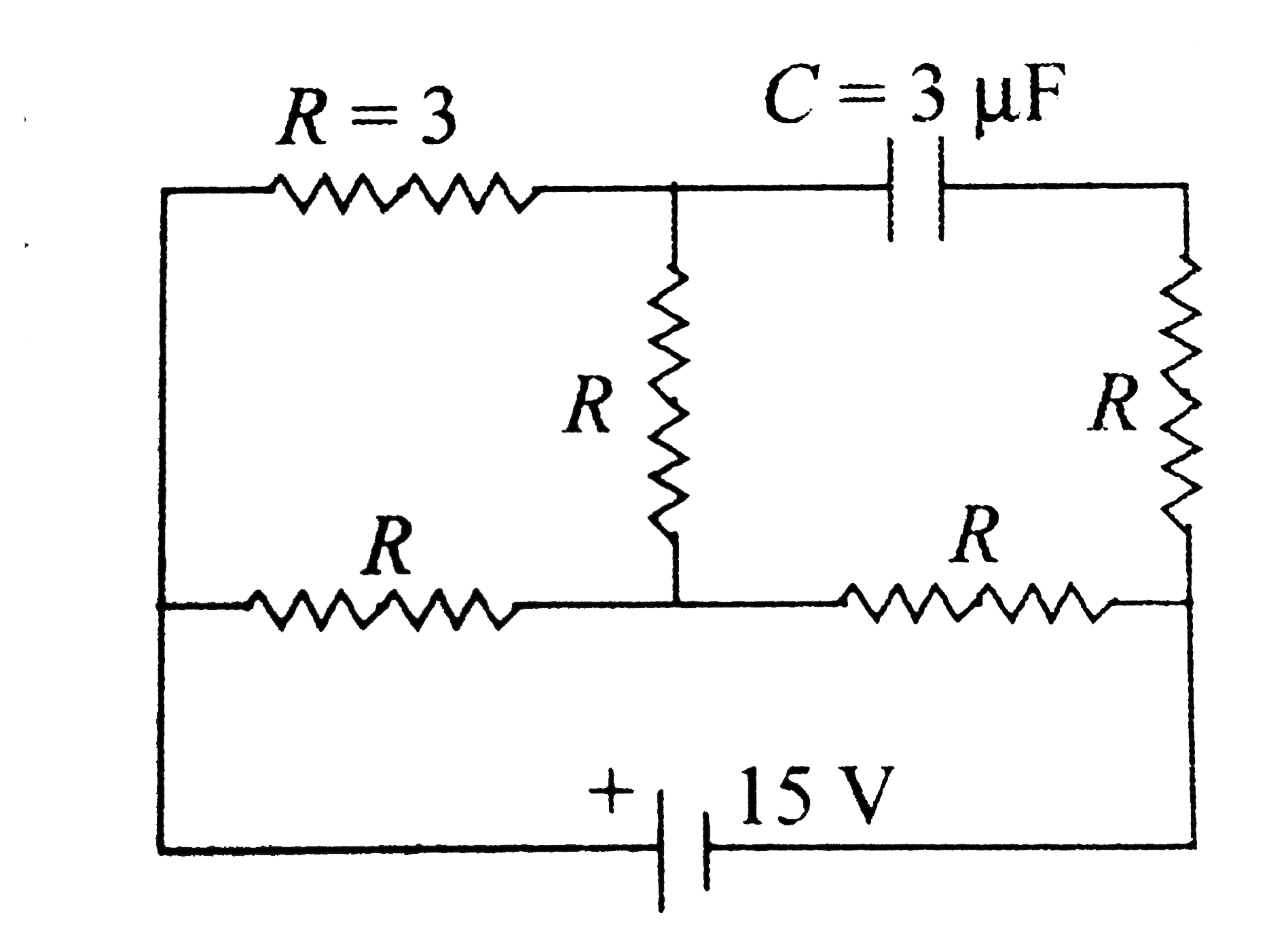
View SolutionIn the circuit shown in fig. the cell is ideal with emf 15V. Each resistance is of 3Ω. The potential difference across the capacitoro in steady state is
View SolutionIn the part of a circuit shown in figure, the potential different
(VG−VH) between points G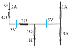
View SolutionA resistor of 6 Ω is connected in series with another resistor of 4 Ω. A potential difference of 20 V is applied across the combination. Calculate :
the current in the circuit,
View Solution

