Calculate the charge on each capacitor and the potential difference across it in the circuits shown in figure for the cases :
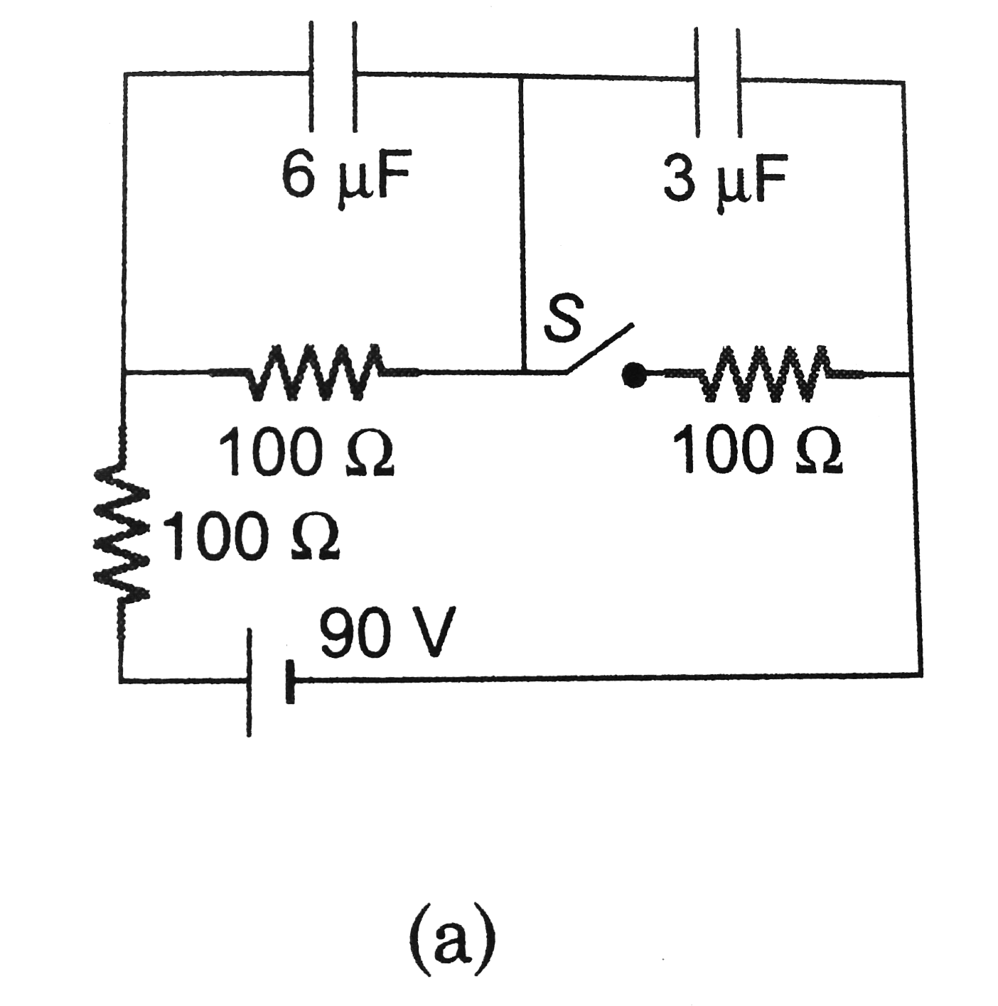
(i) switch S is closed and
(ii) switch S is open.
(iii) In. figure (b), what is the potential of point A when S is open?
The correct Answer is:A
a. Fig a. V6=903=30V,q6=6×30=180μC
V3=903=30V
q3=30×3=90μC
Fig b. Capacitor 1μF is short circuited.
Therefore q1=0
V26=(2020+20+10)×100=40V
This 40V will distribute in inverse ratio of capacity.
∴V6=28×40=10V
V2=68×40=30V
∴q6=60μC,q2=60μC
b. Fig a When S is open 6μF is short-circuited
or V6=0,q6=0
and V3=90V,q3=270μC
Fig b. When S is open V1=100V
q1=100μC
V26=100V
∴V6=28×100=25V
and V2=68×100=75V
∴q6=150μC,q2=150μC
Further, VA−0=V2
∴VA=V2=75V
Topper's Solved these Questions
- CAPACITORSBook:DC PANDEY ENGLISHChapter:CAPACITORSExercise:OBJECTIVE_TYPE
Explore 1 Video
- CAPACITORSBook:DC PANDEY ENGLISHChapter:CAPACITORSExercise:OBJECTIVE_TYPE
Explore 1 Video
- ATOMSBook:DC PANDEY ENGLISHChapter:ATOMSExercise:MEDICAL ENTRANCES GALLERY
Explore 42 Videos
- COMMUNICATION SYSTEMBook:DC PANDEY ENGLISHChapter:COMMUNICATION SYSTEMExercise:Subjective
Explore 11 Videos
Similar Questions
In the circuit shown in figure the switch S is closed at t = 0. A long time after closing the switch
View SolutionAs the switch S is closed in the circuit shown in figure, current passed through it is.
View SolutionIn the circuit diagram shown in figure match the following two columns when switch S is closed.
View SolutionIn the arrangement shown in , the switch S is find
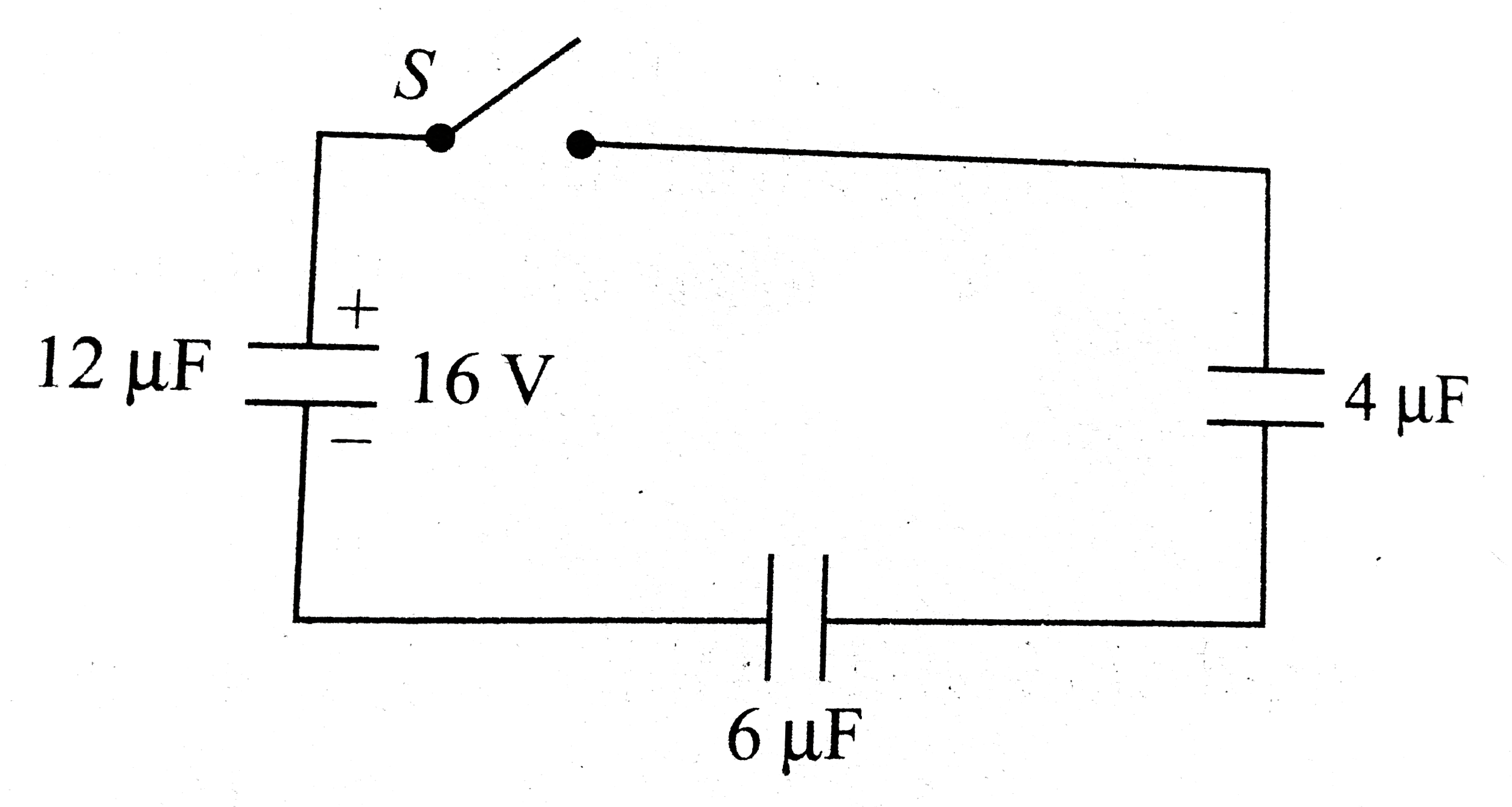 the final potential difference across the 4μF capacitor
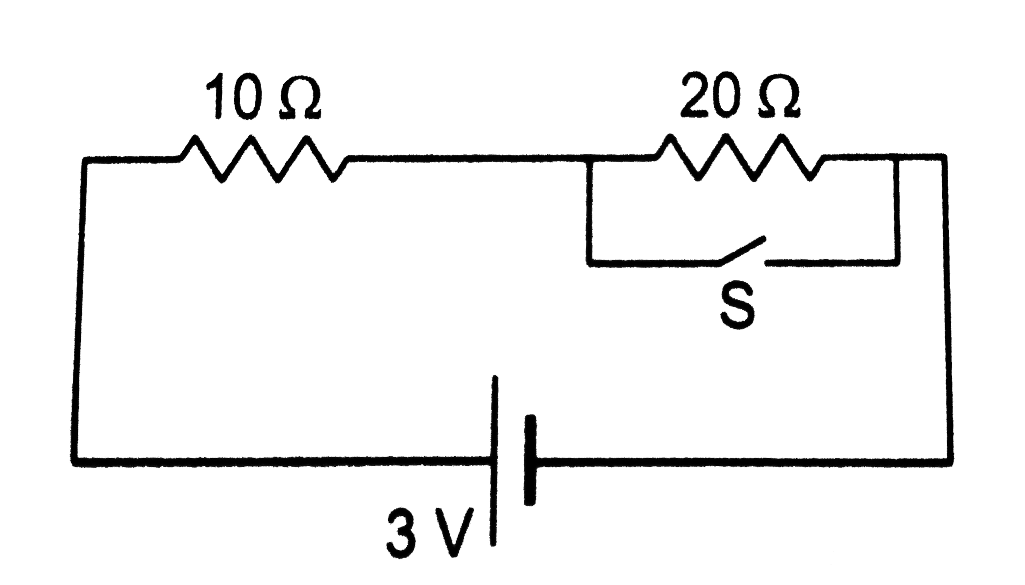
View SolutionConsider the circuit shown in figure.Find the current through the10(Ω)resistor when the switch S is (a)open (b)closed .
View SolutionConsider the circuit shown in figure, after switch S is closed.
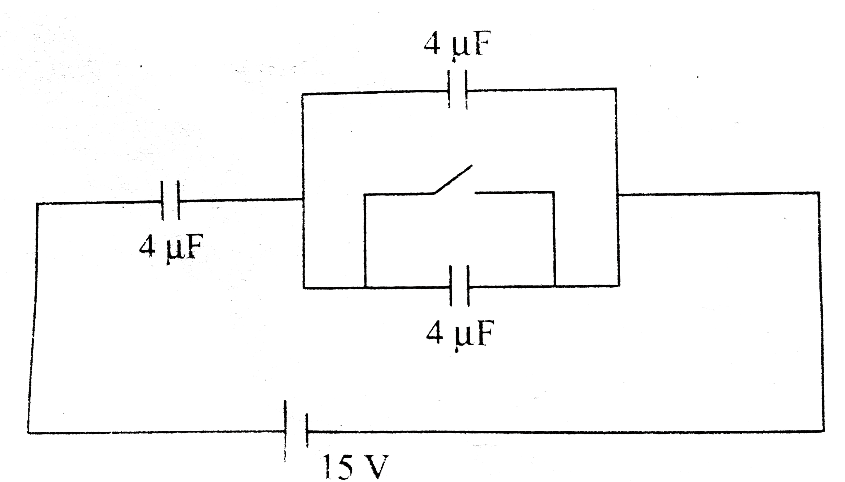
What amount of charge will flow through the switch?
View SolutionIn the circuit shown in figure initially the switch is opened. The switch is closed now.
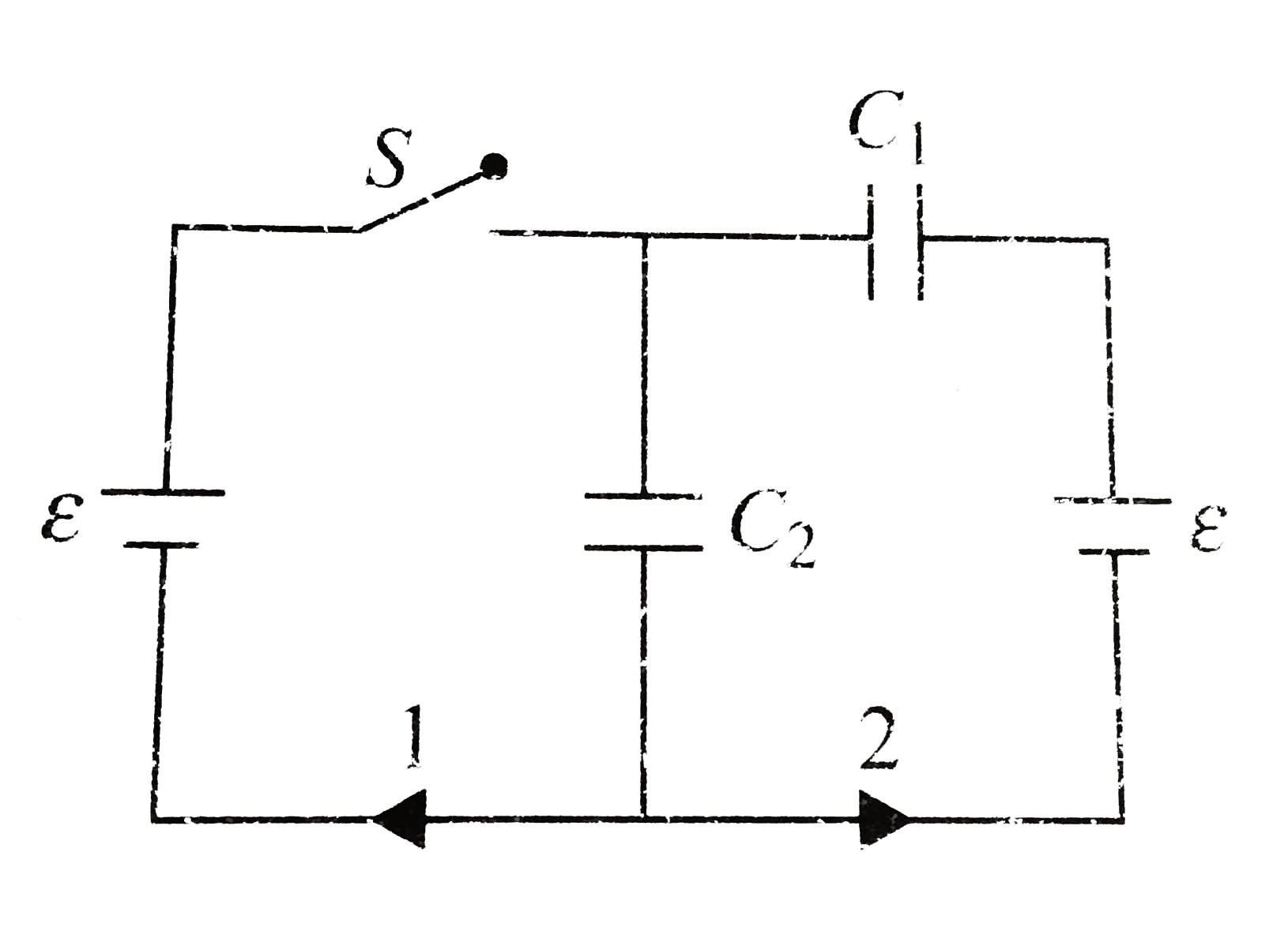
The charge that will flow in direction 1 is
View SolutionIn the circuit shown in figure initially the switch is opened. The switch is closed now.
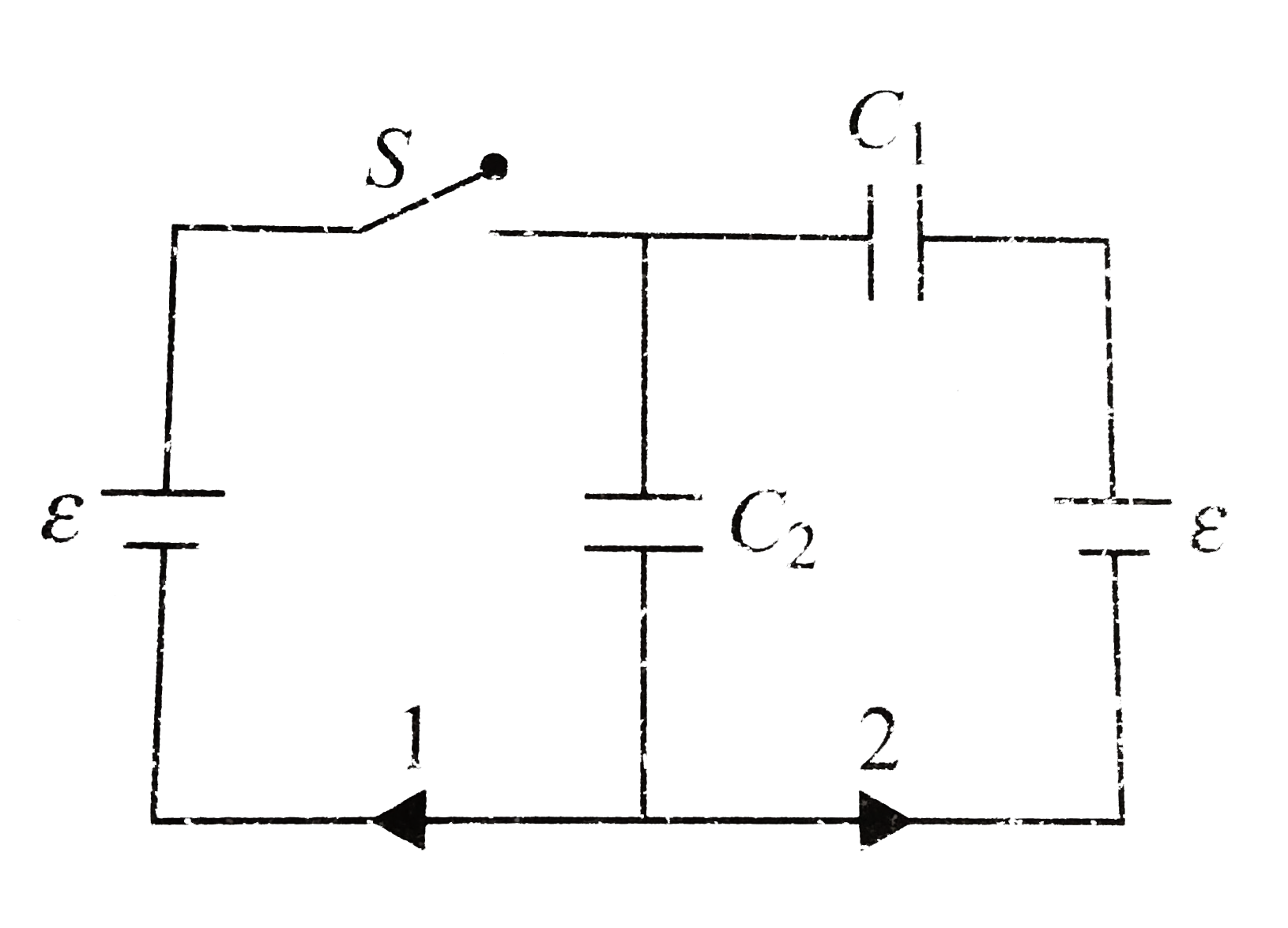
The charge that will flow in direction 2 is
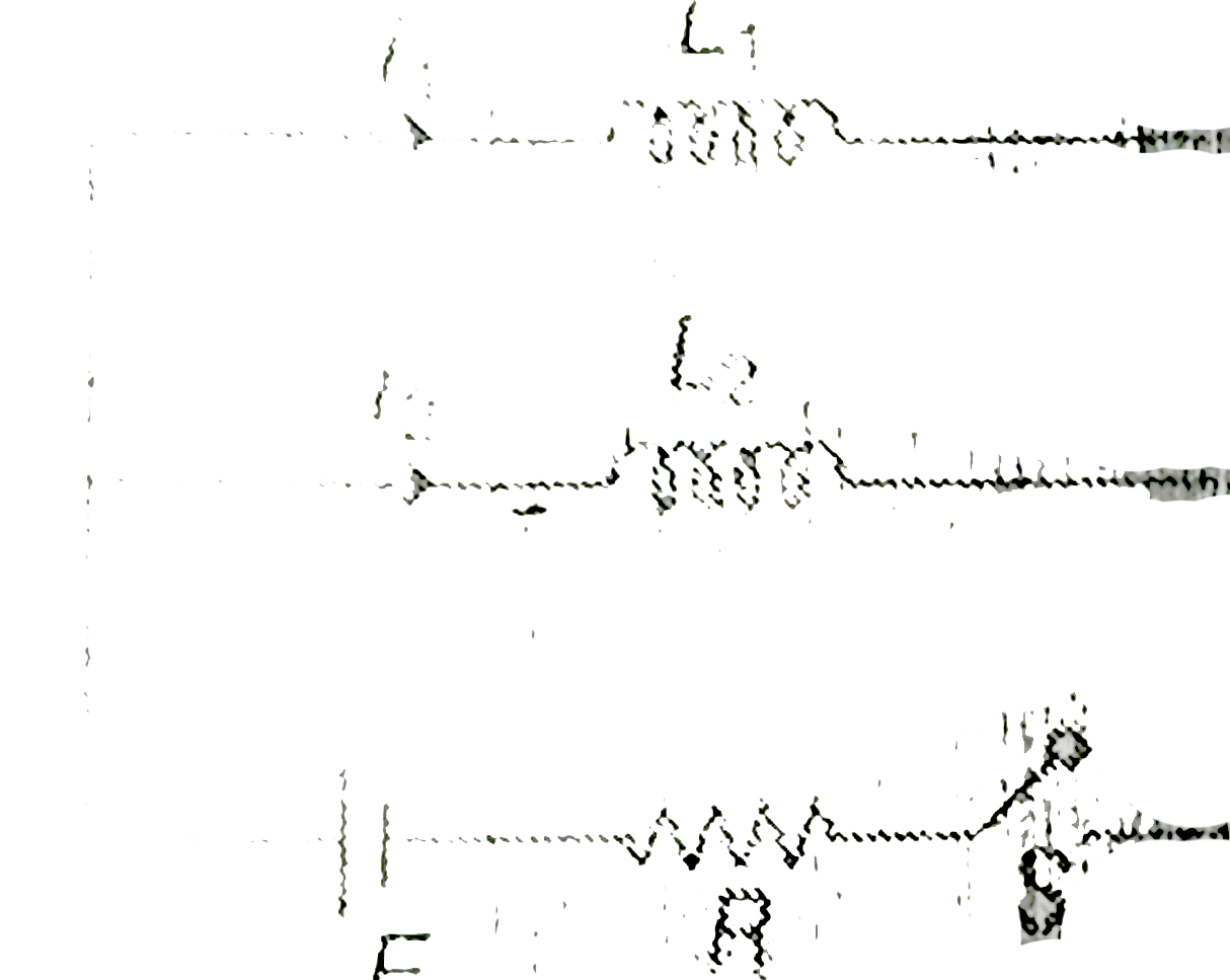
View SolutionIn the circuit shown in the figure The steady state currents i1andi2 in the coils after the switch S is closed are
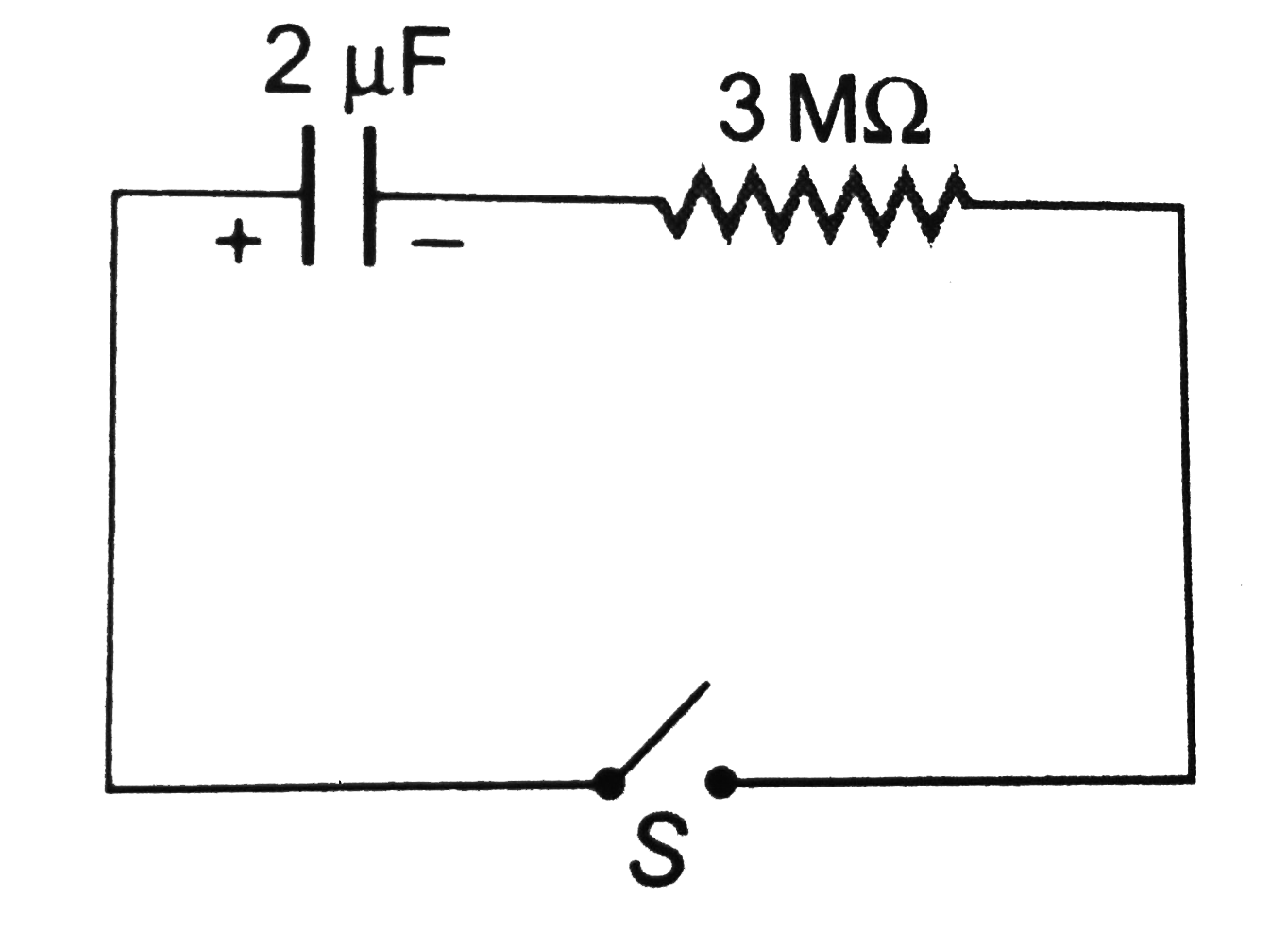
View SolutionIn the circuit shown in figure, the capacitor is charged with a cell of 5V.If the switch is closed at t=0, then at t=12s, charge on the capacitor is
View Solution
