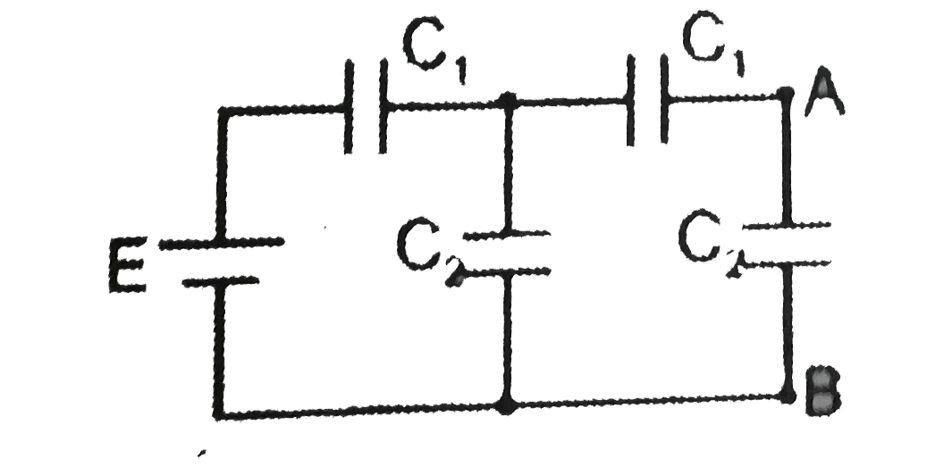
Find the potential difference between points M and N of the system shown in figure, if the emf is equal to E=110V and the capacitance ratio C1C2is2.
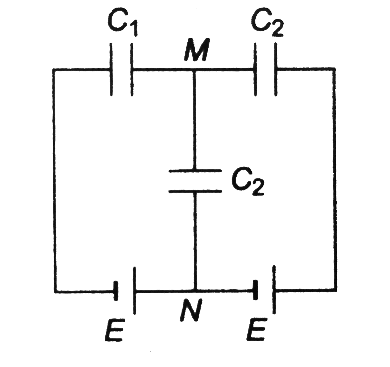
The correct Answer is:A, C
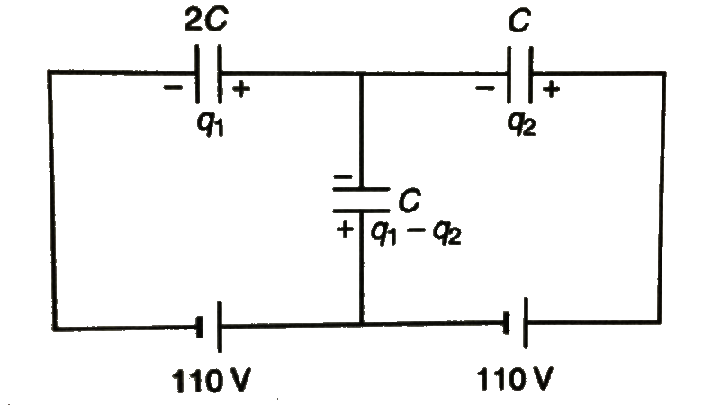
Applying loop law in two closed loops, we have
110−q2C+q1−q2C= or q2=(110C)
and −110+q12C+q1−q2C=0
orq1=(440C3)
potential difference between points M and N is
VN−Vm=q1−q2C
=1103 volt
Topper's Solved these Questions
- CAPACITORSBOOK - DC PANDEY ENGLISHCHAPTER - CAPACITORSEXERCISE - OBJECTIVE_TYPE
1 Video
- CAPACITORSBOOK - DC PANDEY ENGLISHCHAPTER - CAPACITORSEXERCISE - OBJECTIVE_TYPE
1 Video
- ATOMSBOOK - DC PANDEY ENGLISHCHAPTER - ATOMSEXERCISE - MEDICAL ENTRANCES GALLERY
42 Videos
- COMMUNICATION SYSTEMBOOK - DC PANDEY ENGLISHCHAPTER - COMMUNICATION SYSTEMEXERCISE - Subjective
11 Videos
Similar Questions
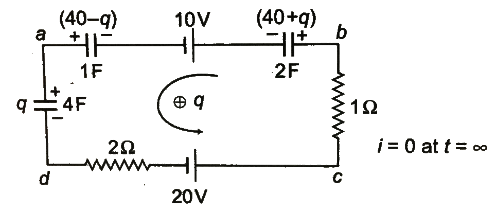
In the circuit shown as potential difference of 60V is appliled across AB. The potential difference between the points M and N is
View SolutionIn the circuit shown as potential difference of 60V is appliled across AB. The potential difference between the points M and N is

View SolutionGiven the value of Rydberg constant is 107m−1, the waves number of the last line of the Balmer series in hydrogen spectrum will be:
View SolutionThe LC product of a tuned amplifier circuit require to generate a carrier wave of 1 MHz for amplitude modulation is
View SolutionA parallel plate capacitor having plates of area S and plate separation d, has capacitance C_1 in air. When two dielectrics of different relative primitivities ( epsilon_1=2 and epsilon_2=4 ) are introduced between the two plates as shown in the figure, the capacitance becomes C_2 . The ratio C_2/C_1 is
View SolutionA circuit has section AB as shown in figure. The emf of the source equals E=10V , the capacitor capacitances are equal to C_1 =1.0muF and C_2=2.0muF , and the potential difference V_A-V_B=5.0V . Find the voltage across each capacitor.
View SolutionThree uncharged capacitors of capacitance C_1,C_2 and C_3 are connected to one another as shown in figure. The potential at O will be
View SolutionFind the potential difference between points M and N of the system shown in figure, if the emf is equal to E=110V and the capacitance ratio C1C2is2.

View SolutionFind the potential difference between points A and B of the system shown in Fig. if the emf is equal to E = 100V and the capacitance ratio C_(2)//C_(1) = eta = 2.0 .
View SolutionIn the circuit shown in the figure, the potential difference between points aandb is Va−Vb=4V. Find the emf, E of the battery.
View SolutionFind the potential difference between points M and N of the circuit shown in figure. The battery voltage is equal to xi and the capacitance ratio C_(2)//C_(1) is equal to eta
View SolutionFind the potential difference between the points a and b of the circuit in figure 6.25 when the battery has an emf of 110 V.
View SolutionFind the potential difference between points A and B (in V) of the system shown in figure if the emf is equal to E=110 V and the capacitance ratio C2/C1=η=2.0.
View Solutionचित्र 2.5 में प्रदर्शित व्यवस्था में 6μF धारिता के संधरित्र की प्लेटो के बीच विभवांतर V है तथा A एव B बिन्दुओ के बीच तुल्य धारिता X है।
View SolutionA capacitor of capacitance C1 is charged up to potential V and then connected in parallel to an uncharged capacitor or capacitance C2. The final potential difference across each capacitor will be
View Solution

