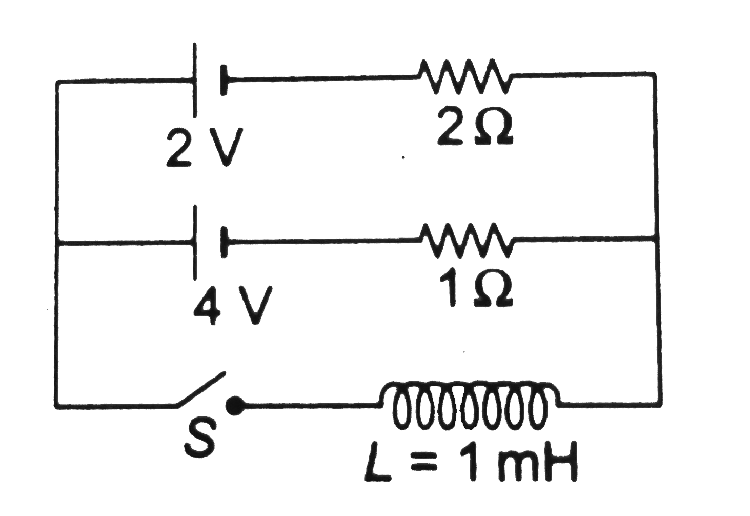
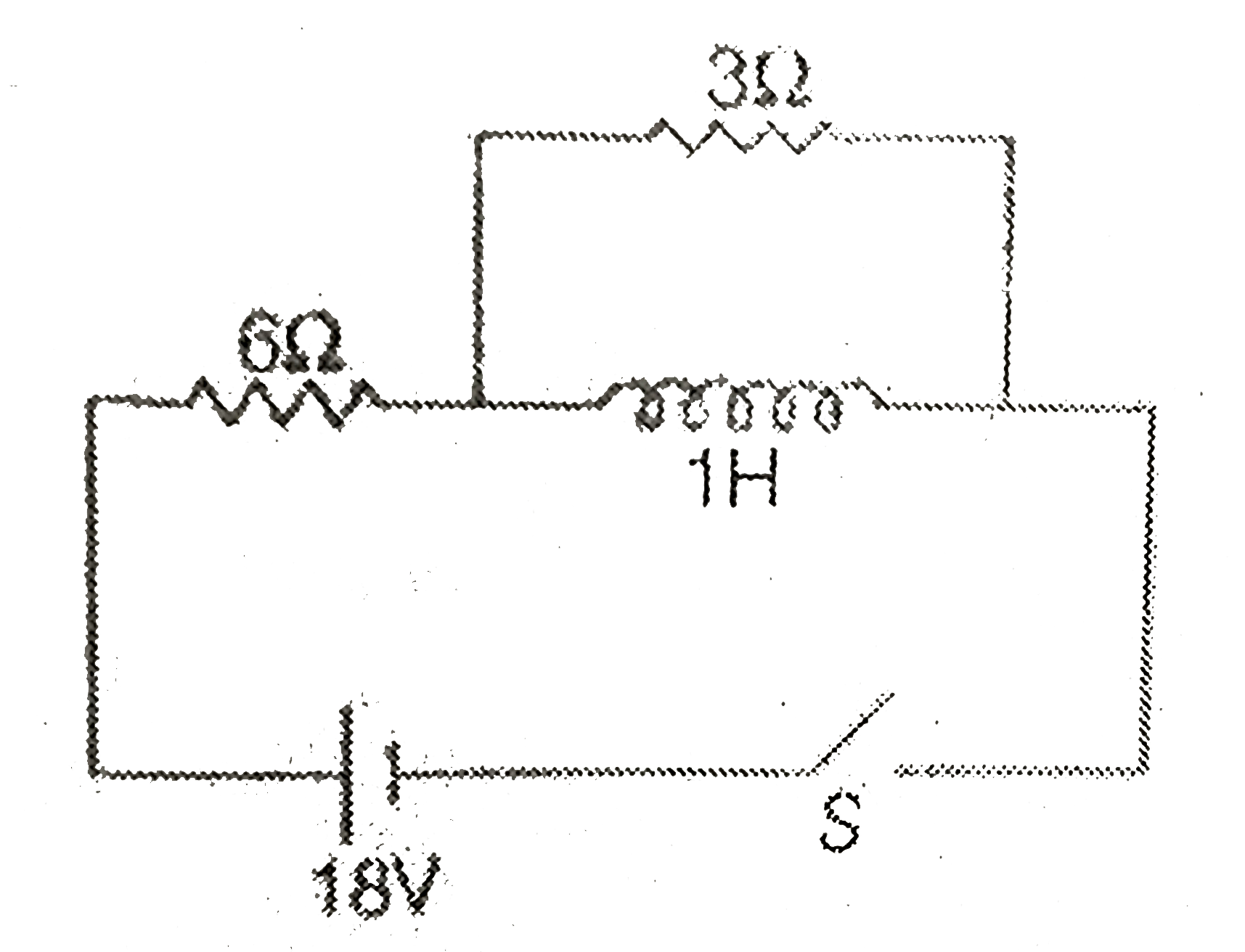
In the circuit shown, switch S is closed at time t=0. Find the current through the inductor as a function of time t.
The correct Answer is:A, B, C
At t=0, Current through inductor will be zero.
At t=∞ net emf =2/2+4/11/2+1/1=103V
Net resistance =2×12+1=23Ω
∴i=10/32/3=5A
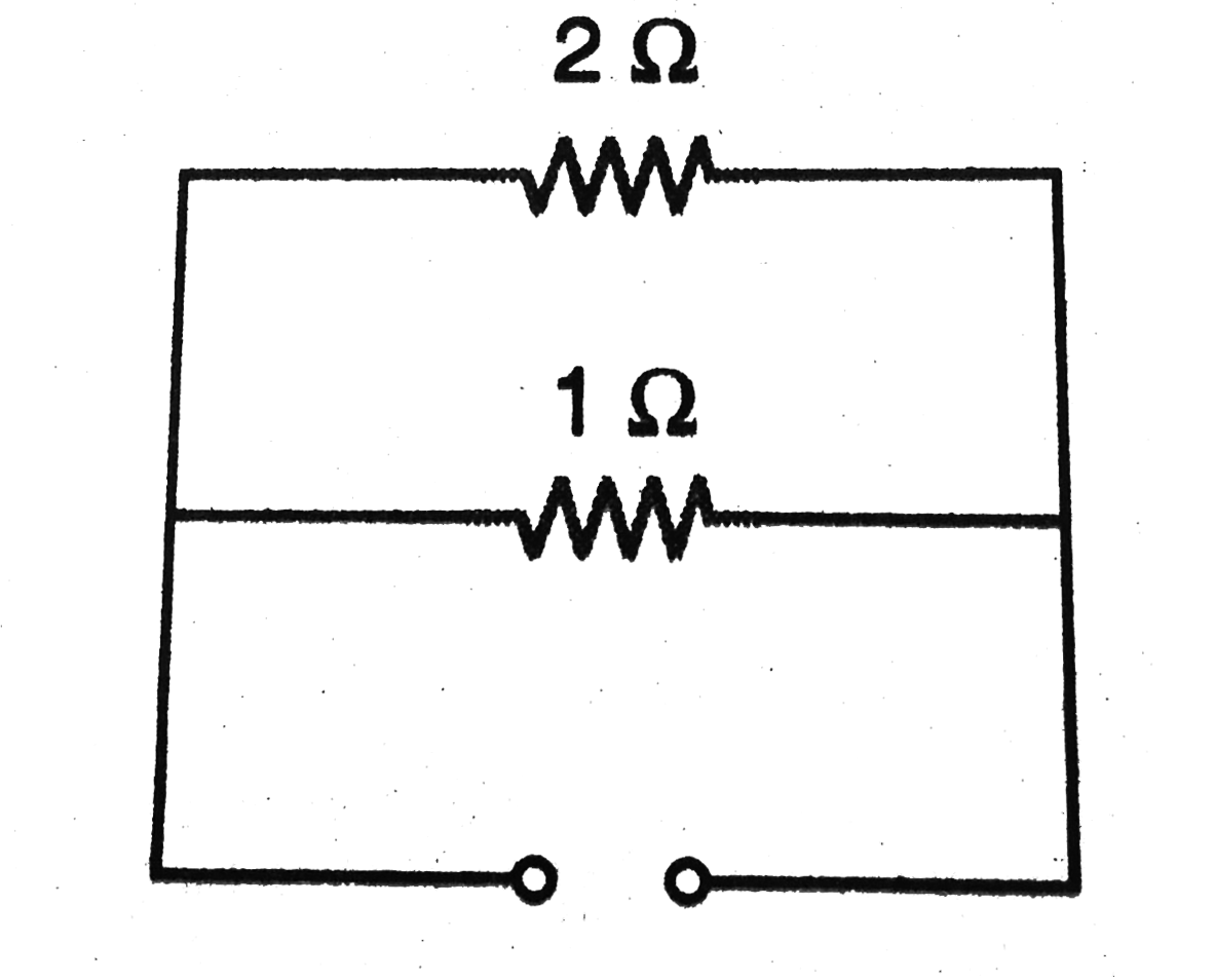
To find equivalent time constant short circuit, both the batteries and find net resistance across inductor.
Rnet=2×12+1=23Ω
∴τL=LRnet=1×10−323=32000s
Current through inductor will increase exponentially from 0 to 5 A.
∴i=5(1−e−2000t3)
टॉपर्स ने हल किए ये सवाल
- ELECTROMAGNETIC INDUCTIONBook:DC PANDEY ENGLISHChapter:ELECTROMAGNETIC INDUCTIONExercise:Check point
Explore 60 Videos
- ELECTROMAGNETIC INDUCTIONBook:DC PANDEY ENGLISHChapter:ELECTROMAGNETIC INDUCTIONExercise:Taking it together
Explore 119 Videos
- ELECTROMAGNETIC INDUCTIONBook:DC PANDEY ENGLISHChapter:ELECTROMAGNETIC INDUCTIONExercise:SUBJECTIVE TYPE
Explore 1 Video
- CURRENT ELECTRICITYBook:DC PANDEY ENGLISHChapter:CURRENT ELECTRICITYExercise:Medical entrances gallery
Explore 97 Videos
- ELECTROMAGNETIC WAVESBook:DC PANDEY ENGLISHChapter:ELECTROMAGNETIC WAVESExercise:Sec C
Explore 22 Videos
समान प्रश्न
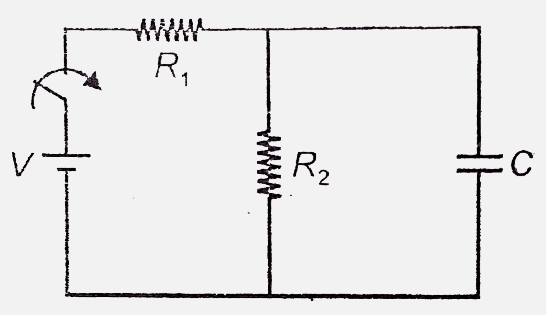
Consider the circuit shown. Switch is closed at t=0. Find the current through the battery as a function of time. Initially capacitor was uncharged.
View Solution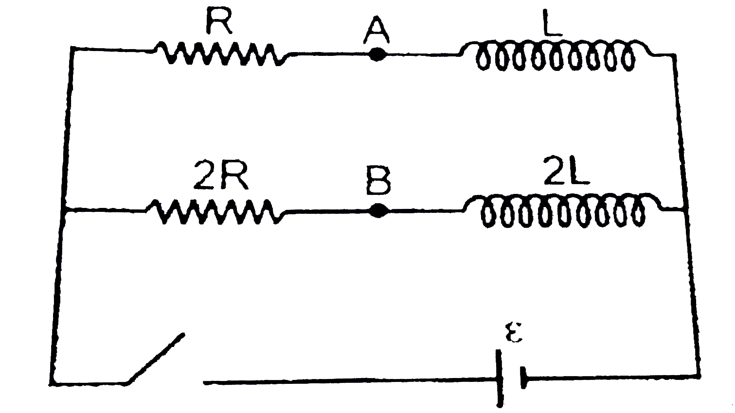
In given LR circuit the switch S is closed at time t=0 then
View SolutionIn the circuit shown in figure switch S is closed at time t=0
Takin left to right current through the indcutor as apositive current, current through inductor varies with time as
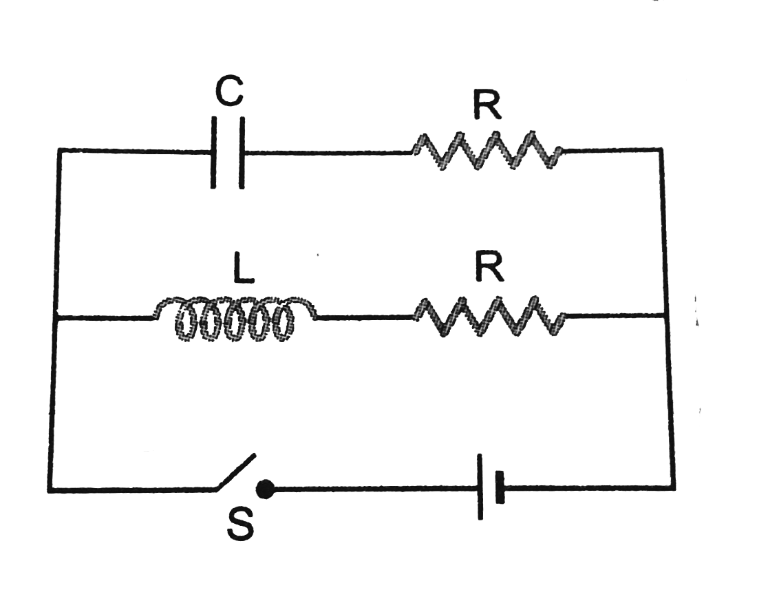
View SolutionIn the circuit shown if Fig. the switch S is closed at time t = 0. The current through the capacitor and inductor will be equal at time t equal (given R=√L/C
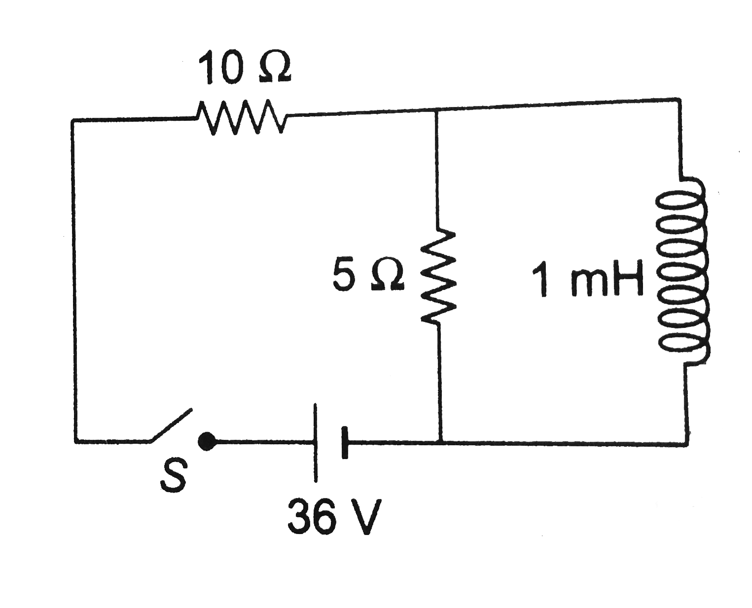
View SolutionIn the circuit arrangement shown in figure, the switch S is closed at t=0. Find the current in the inductance as a function of time? Does the current through 10Ω resistor vary with time or remains constant.
View SolutionIn the circuit shown, the switch 'S' is closed at t=0. Then the current through the battery steady state reached is
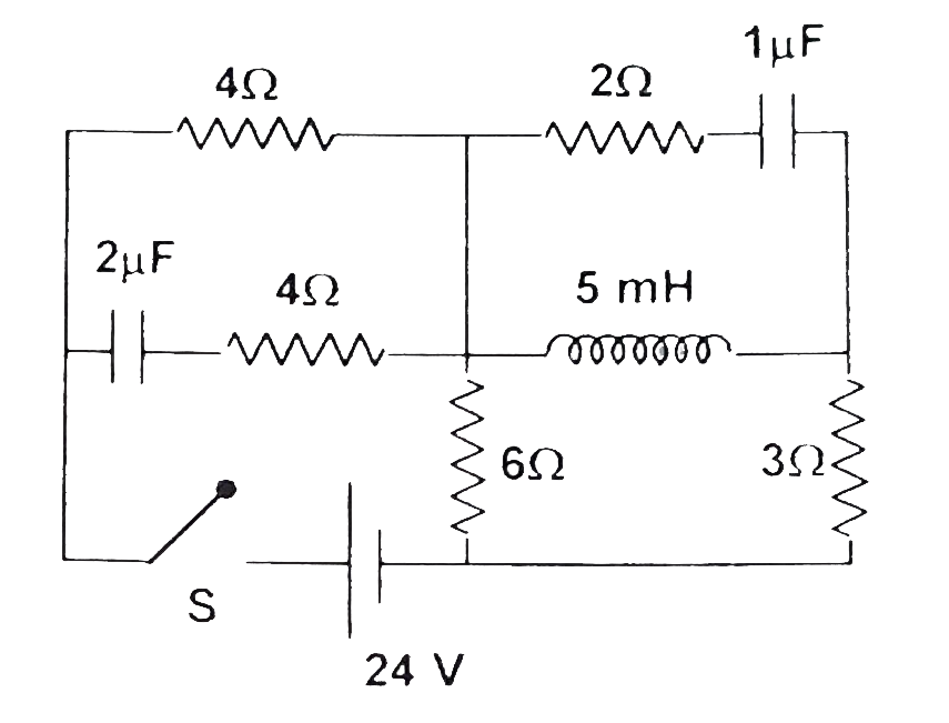
View Solutionthere in no current part of this circuit for time t<o. Switch S is closed at t=0.
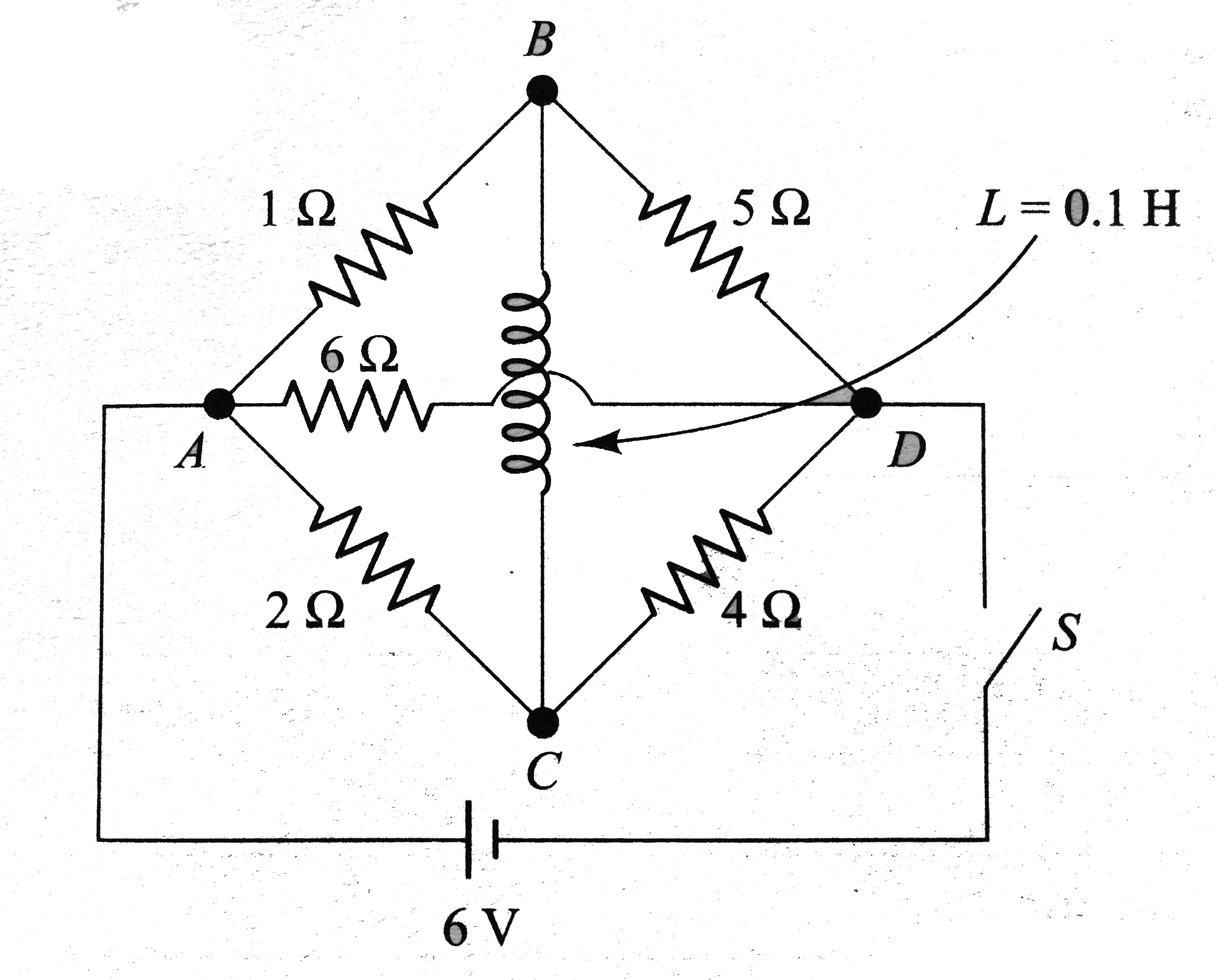
The current through the inductor after a long time will be
View SolutionIn the circuit shown in figure-3.240 switch S is closed at time t=0. find the current through different wires and charge stored on the capacitor at any time t.
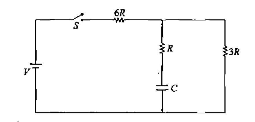
View SolutionIn the circuit shown in the figure, switch S is closed at time t=0. Select the correct statements.
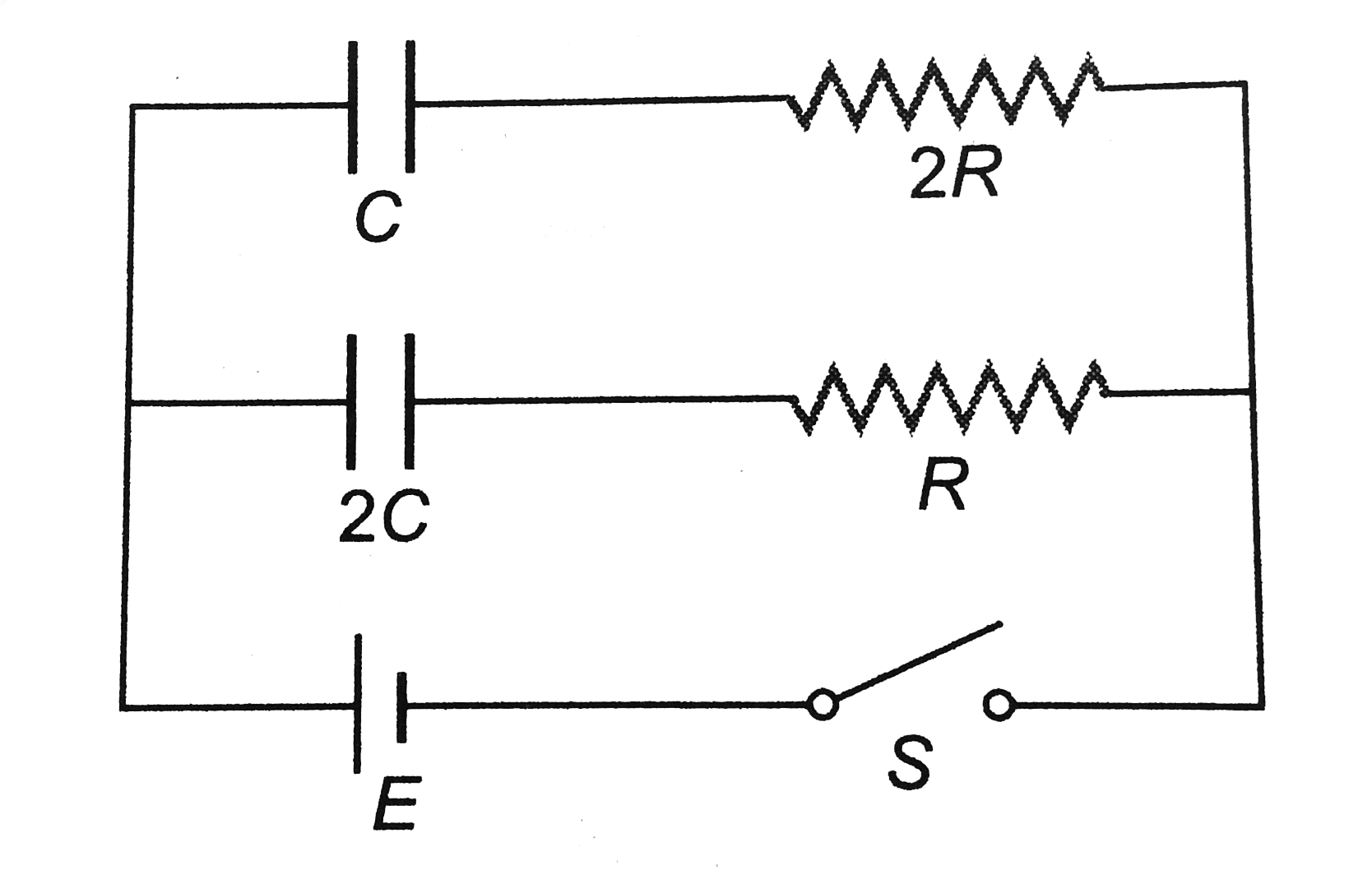
View SolutionIn the circuit shown in the figure, switch S is closed at time t=0. Select the correct statements.

View Solution
