Let V and I be the readings of the voltmeter and the ammeter respectively as shown in the figure. Let RV and RA be their corresponding resistancce Therefore,
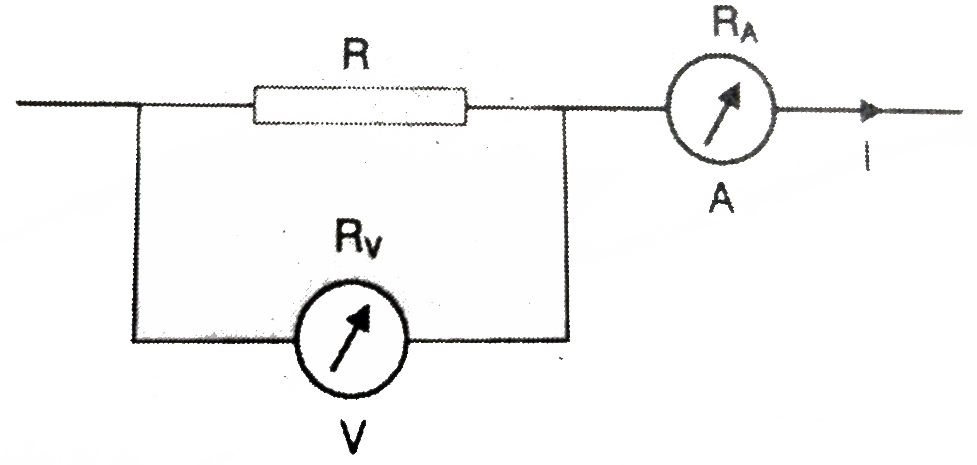
R=VI
R=VI−(VRV)
R=RV−RA
R=V(R+RA)IRA
Step by step video solution for Let V and I be the readings of the voltmeter and the ammeter respectively as shown in the figure. Let R_(V) " and "R_(A) be their corresponding resistancce Therefore, by Physics experts to help you in doubts & scoring excellent marks in Class 12 exams.
Updated on:21/07/2023Topper's Solved these Questions
Similar Questions
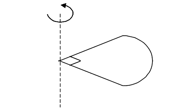
One quarter sector is cut from a uniform circular disc of radius R. This sector has mass M. it is made to rotate about a line perpendicular to its plane and passing through the center of the original disc. Its moment of inertia about the axis of rotation is
View SolutionAn ice cube floats on water in a beaker with 9/10 th of its volume submerged under water. What fraction of its volume will be submerged, if the beaker of water is taken to the Moon where the gravity is 1/6th that on the Earth?
View SolutionA students connects an ammeter A and a voltmeter V to measure a resistancer as shown in figure. If the voltmeter reads 20V and the ammeter reads 4A, then R is
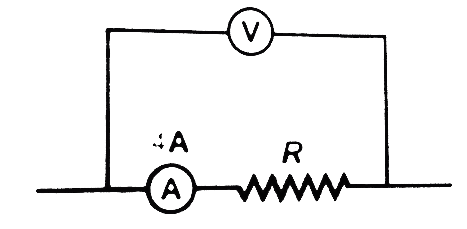
View SolutionThe value of resistance of an unknown resistor is calculated using the formula R = V//I where V and I are the readings of the voltmeter and the ammeter, respectivley. Consider the circuits below. The internal resistances of the voltmeter and the ammeter (R_V and R_G, respectively) are finite and nonzero. , Let R_(A) and R_(B) be the calculated values in the two cases A and B , respectively. If the resistance of voltmeter is R_(V) = 1k Omega and the percentage error in the measurement of R (the value of R is nearly 10 Omega )is
View SolutionIn the, Ohm's law experiment ot find resistance of unknown resistor R, the arrangement is as shown. The resistance measured is given by R_("measured")=(V)/(i)V= voltage reading of voltmeter. i=current reading of ammeter. The ammeters and the voltmeter used are not ideal, and have resistance R_(A) and R_(V) respectively. For arrangement shown, the meausred resistance is
View SolutionA voltmeter of resistance R_(V) and an ammeter of resistance R_(A) are connected as shown in an attempt to measure the resistance R . The measured value of the resistance is R_(M) = (V)/(I_(0)) where V is reading of voltmeter and I_(0) is reading of the ammeter. find the true value of the resistance in terms of R_(M), R_(V) and R_(A) .
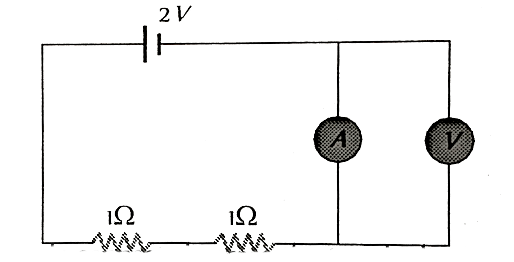
View SolutionIn the circuit shown, A and V are ideal ammeter and voltmeter respectively. Reading of the voltmeter will be
View SolutionThe power dissipated in resistor R_(3) shown in the figure is 15 W. The reading the ammeter is 500 mA and the reading of the voltmeter is 10 V. Ammeter, voltmeter and battery are ideal. Find the resistance R_(1)
View SolutionThe power dissipated in resistor R_(3) shown in the figure is 15 W. The reading the ammeter is 500 mA and the reading of the voltmeter is 10 V. Ammeter, voltmeter and battery are ideal. Find the resistance R_(3)
View SolutionAn ammeter A, a voltmeter V and a resistance R are connected as shown in the figure. If the voltmeter reading is 1.6V and the ammeter reading is 0.4A, then R is
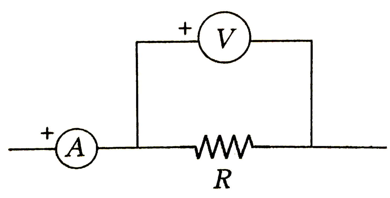
View SolutionLet V and I be the readings of the voltmeter and the ammeter respectively as shown in the figure. Let R_(V) " and "R_(A) be their corresponding resistancce Therefore,
View SolutionIn the circuit shown, A and V are ideal ammeter and voltmeter respectively. Reading of the voltmeter will be
View SolutionThe power dissipated in resistor R_(3) shown in the figure is 15 W. The reading the ammeter is 500 mA and the reading of the voltmeter is 10 V. Ammeter, voltmeter and battery are ideal. Find the resistance R_(3)
View SolutionThe power dissipated in resistor R_(3) shown in the figure is 15 W. The reading the ammeter is 500 mA and the reading of the voltmeter is 10 V. Ammeter, voltmeter and battery are ideal. Find the resistance R_(1)
View SolutionIn the circuit shown, A and V are ideal ammeter and voltmeter respectively. Reading of the voltmeter will be
View SolutionAn ammeter A, a voltmeter V and a resistance R are connected as shown in the figure. If the voltmeter reading is 1.6V and the ammeter reading is 0.4 A, then R is
View Solution
