The circuit as shown in the figure is equivalent to

A
AND gate
B
NOR gate
C
OR gate
D
NAND gate
Video Solution
Text Solution
The correct Answer is:D
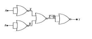
Y=¯¯¯¯¯¯¯¯¯¯¯¯¯¯¯¯¯¯¯¯¯¯¯¯¯¯¯A+¯¯¯B+¯¯¯A+¯¯¯B=¯¯¯¯¯¯¯¯A.B
It is a Boolean expression for NAND gate.
|
Similar Questions
Knowledge Check
The circuit as shown in figure is equivalent to
 ANOR gateBOR gateCAND gateDNAND gate
The circuit as shown in figure is equivalent to
 AOR gateBNOR gateCNAND gateDAND gate
The circuit shown in the figure acts as
 AOR gateBAND gateCNOT gateDNAND gate
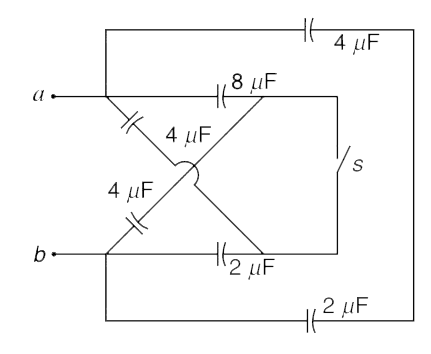
In the circuit shown in the Figure find the equivalent capacitance between points a and b when–
(a) Switch S is open.
(b) Switch S is closed.
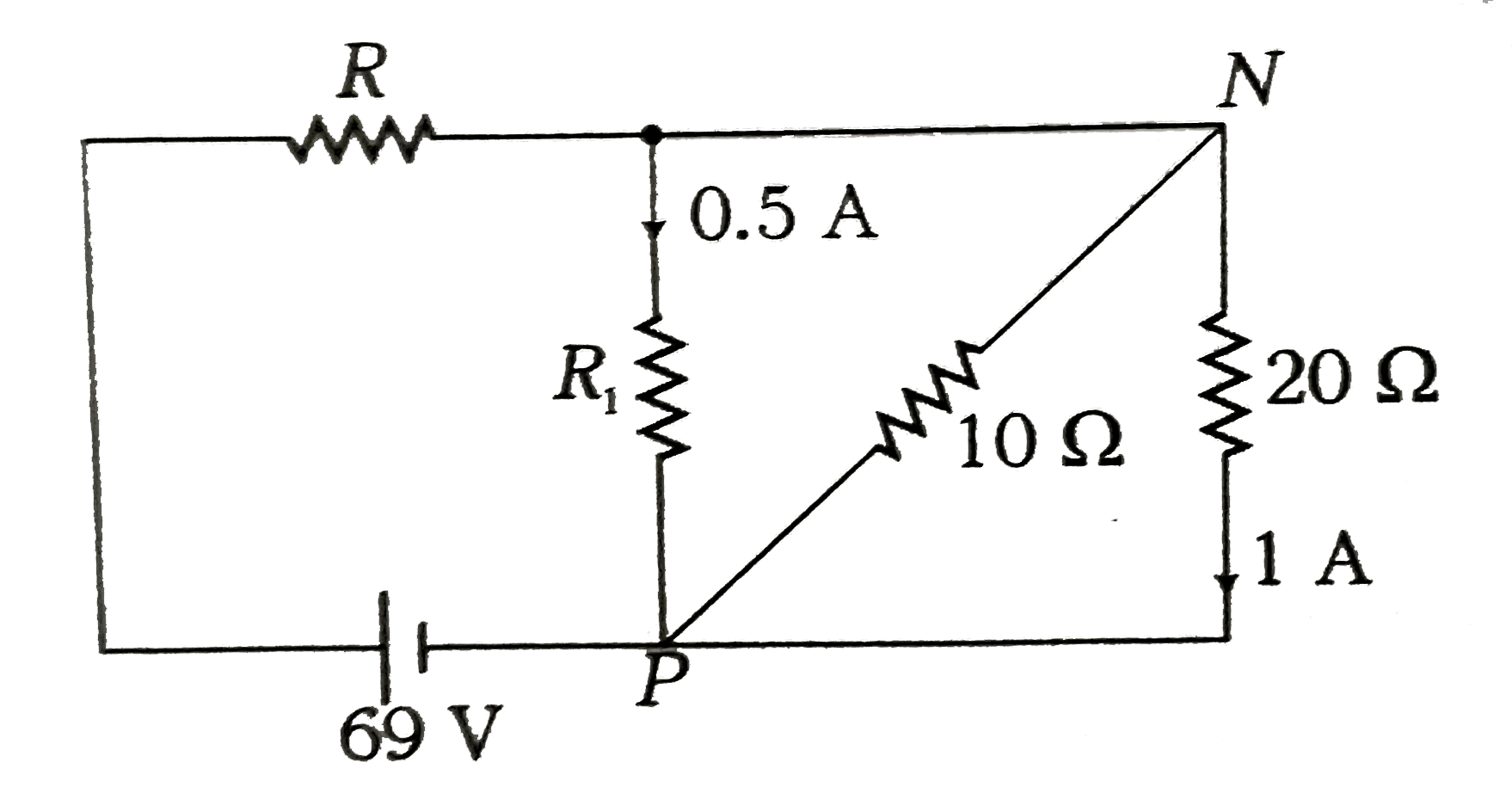
View SolutionIn the circuit shown in the figure,
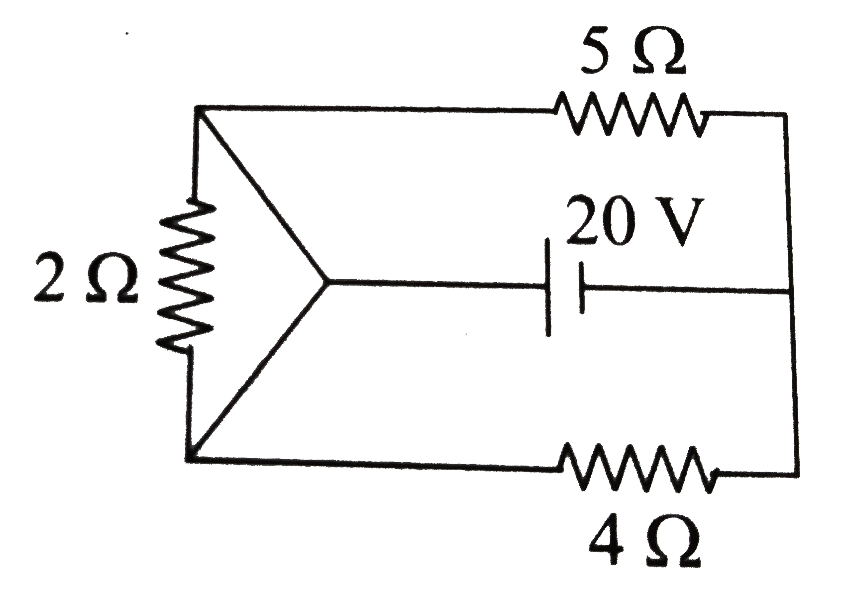
View SolutionIn the circuit shown in the figure
 .
.
View Solution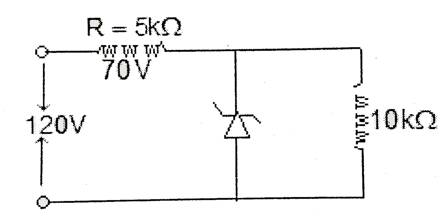
For the circuit shown in the figure:
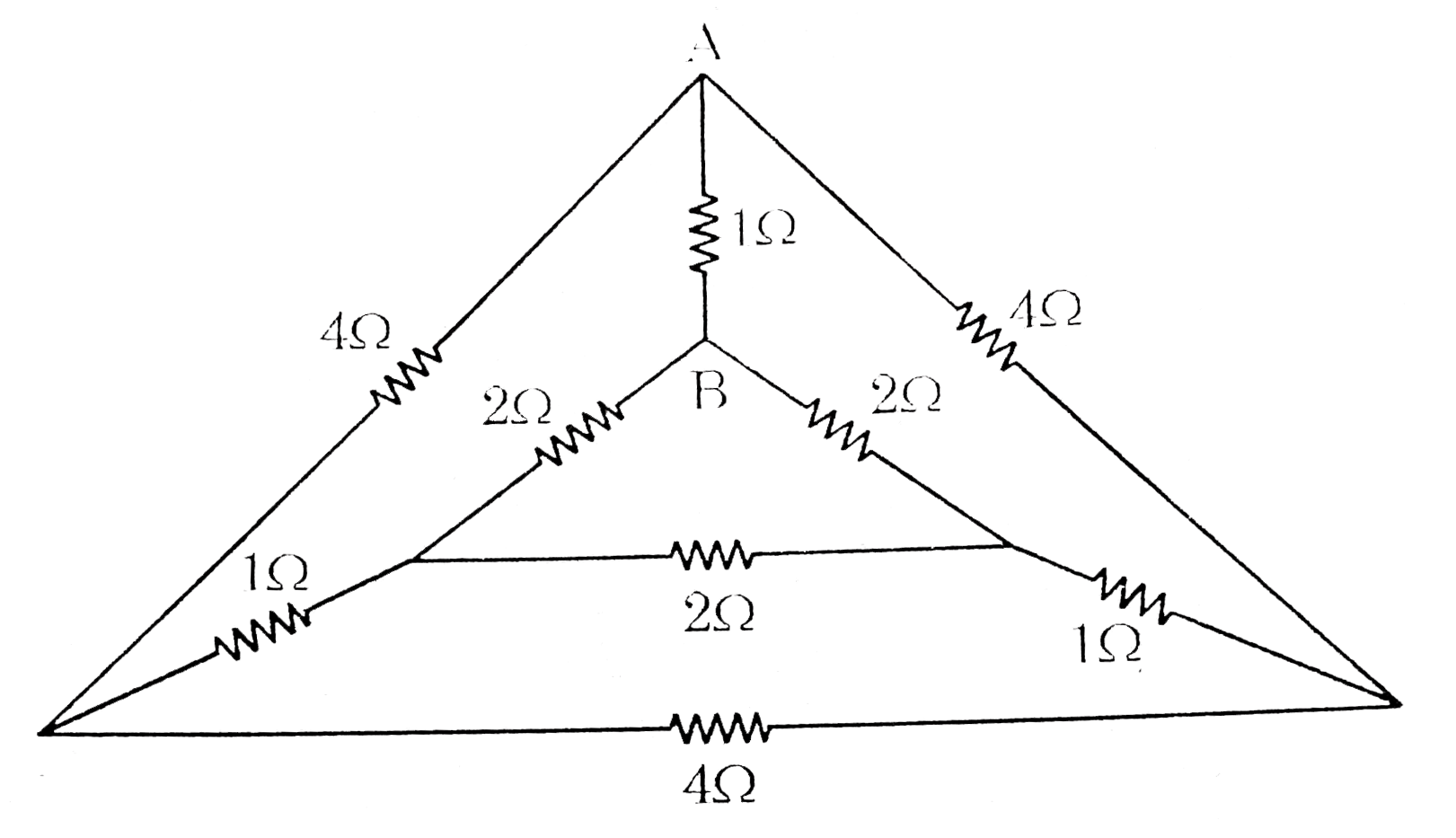
View SolutionConsider the circuit as shown in figure. The equivalent resistance between A and B is
View Solution


