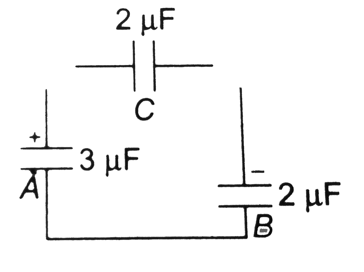
Two capacitors A and B with capacities C1andC2 are charged to potential difference of V1andV2 respectively. The plates of the capacitors are connected as shown in the figure with one wire free from each capacitor. The upper plate of A is positive and that of B is negative. An uncharged capacitor of capacitance C3 and lead wires falls on the free ends to complete circuit, then
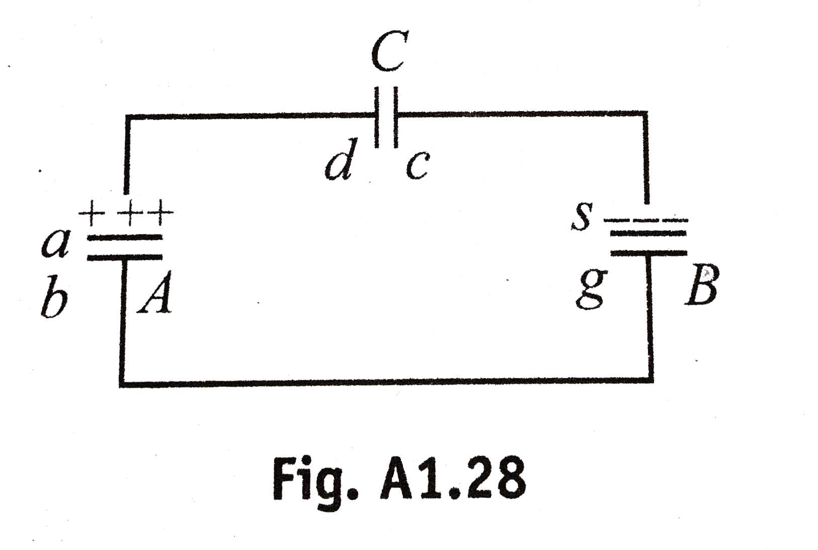
the final charge on each capacitor are same to each other
the final sum of charge on plates a and d is C1V1.
the final sum of charge on plates b and g is C2V2−C1V1
both (b) and(c ) are correct.
The correct Answer is:D
d. Charge on positive plate of A is C1V1.
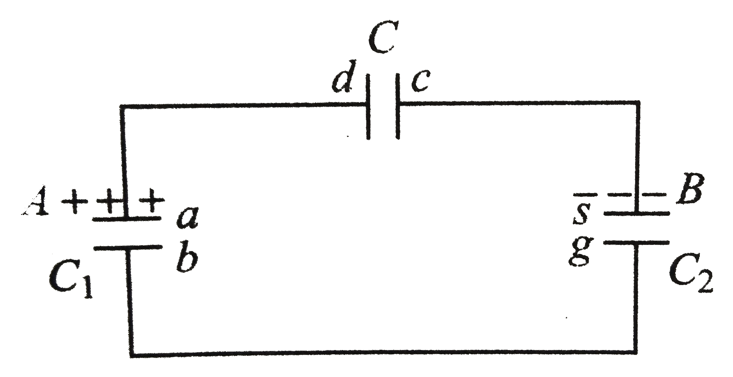
Charge on negative plate of B is −C2V3. When d plate of capacitor C is connected with the plate of , then the total charge of (d,a) plate system will be C1V1 (conservation of charge). Similarty on (c,s) plates, total charge will be −C2V2. The total charge on (h,g) plate system will be +C2V2−C1V1.
Topper's Solved these Questions
- MISCELLANEOUS VOLUME 3BOOK - CENGAGE PHYSICSCHAPTER - MISCELLANEOUS VOLUME 3EXERCISE - Multiple Correct Answer type
109 Videos
- MISCELLANEOUS VOLUME 3BOOK - CENGAGE PHYSICSCHAPTER - MISCELLANEOUS VOLUME 3EXERCISE - Assertion and Reason Type
8 Videos
- MECHANICAL PROPERTIES OF SOLIDSBOOK - CENGAGE PHYSICSCHAPTER - MECHANICAL PROPERTIES OF SOLIDSEXERCISE - Question Bank
4 Videos
- MISCELLANEOUS VOLUME 5BOOK - CENGAGE PHYSICSCHAPTER - MISCELLANEOUS VOLUME 5EXERCISE - Integer
12 Videos
Similar Questions
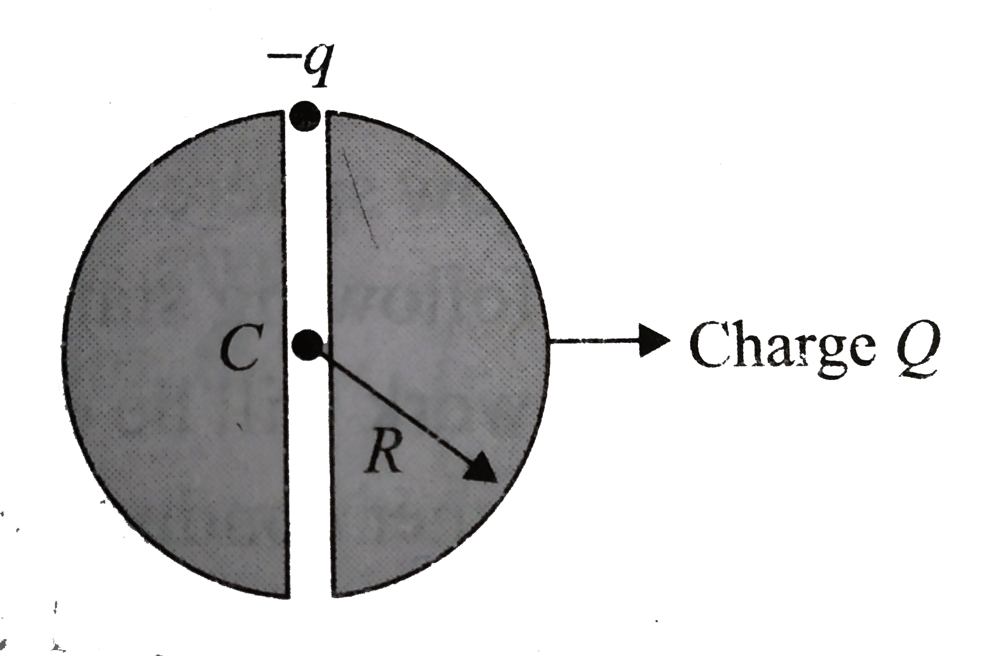
In a uniformly charged dielectric sphere, a very thin tunnel has been made along the diameter as shown in figure. A charge particle −q having mass m is released from rest at one end of the tunnel. For the situation described, mark the correct statement(s), (neglect gravity).
View SolutionStatement I: When air between the plates of a parallel plate condenser is replaced by an insulating dielectric medium, its capacity decreases.
Statement II: Electric field intensity between the plates with dielectric in between is reduced.
View SolutionThe diameter of a brass rod is 4 mm and Young's modulus of brass is 9×10¹⁰N/m2. The force required to stretch by 0.1 % of its length is
View SolutionA charged particle enters a uniform magnetic field with velocity v0=4m/s perpendicular to it, the length of magnetic field is x=(√32)R, where R is the radius of the circular path of the particle in the field. Find the magnitude of charge in velocity (in m/s) of the particle when it comes out of the field.
View SolutionThree uncharged capacitors of capacitance C_1,C_2 and C_3 are connected to one another as shown in figure. The potential at O will be
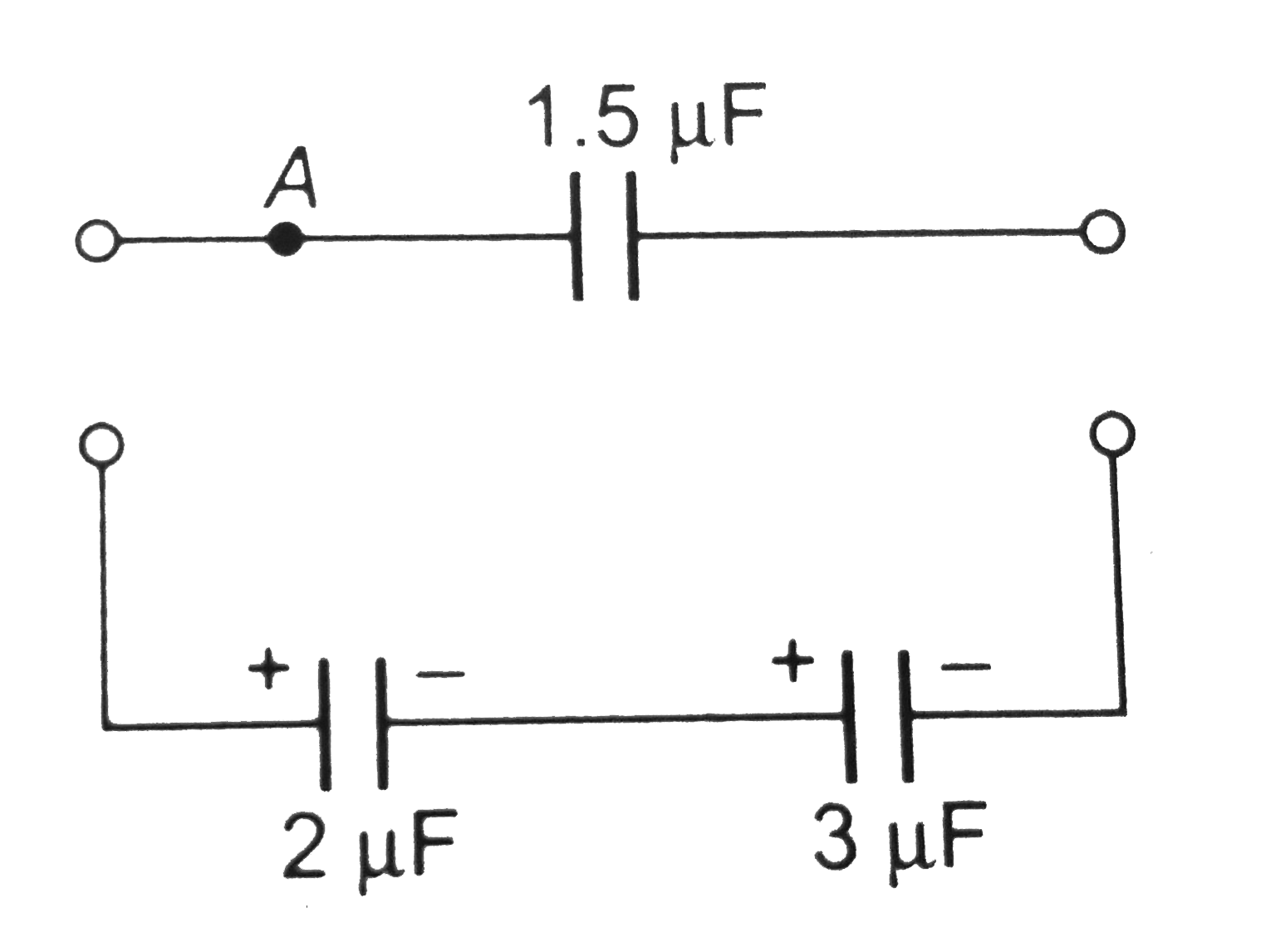
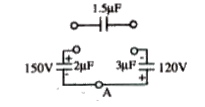
View SolutionTwo capacitors of 2μF and 3μF are charged to 150V and 120V, respectively. The plates of capacitor are connected as shown in the figure. An uncharged capacitor of capacity 1.5μF falls to the free end of the wire. Then
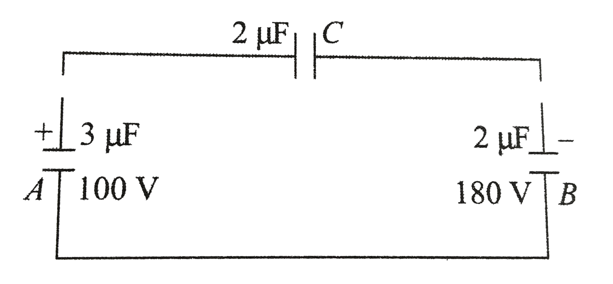
View SolutionTwo capacitors A and B with capacities 3μF and 2μF are charged to a potential difference of 100V and 180V, respectively. The plates of the capacitors are connected as show in figure with one wire of each capacitor free. The upper plate of A is positive and that of B is negastive. An uncharged 2μF capcitor C with lead wires falls on the free ends to complete the circuit. Calculate
a. the final charge on the three capacitors.
b. the amount of electrostatic energy stored in the system before and after completion of the circuit.
View SolutionTwo capacitors A and B with capacities 3μF and 2μF are charged to a potential differece of 100V and 180V, respectively. The plates ot the capacitors are connected as shown in, with one wire free from each capacitor. The upper plate of A is positive and that of B is negative An uncharged 2μF capacitor C with lead wires falls on the free ends to complete the circuit.
i. Calculate the final charge on the three capacitors,
ii. Find the amount of electrostatic energy stored in the system before and after the completion of the circuit.
 .
.
View SolutionA capacitor of capacitance C1 is charged up to potential V and then connected in parallel to an uncharged capacitor or capacitance C2. The final potential difference across each capacitor will be
View Solutionदो संधारित्र A तथा B जिनकी धारिताये क्रमशः 31muF" तथा "21muF हैं, क्रमश: 100 वोल्ट व 180 वोल्ट विभवान्तर तक आवेशित किये गये हैं संधारित्रों की प्लेटों को चित्रानुसार सम्बन्धित किया गया है तथा प्रत्येक का एक तार स्वतंत्र छोड़ दिया गया है। A की ऊपरी प्लेट धनात्मक तथा B की ऊपरी प्लेट ऋणात्मक है एक निरावेशित 2μF का संधारित्र C जिसकी दोनों प्लेटो में चालक तार (lead wires) लगे है, परिपथ को पूरा करने के लिए मुक्त तारो पर गिरता है। गणना कीजिये।
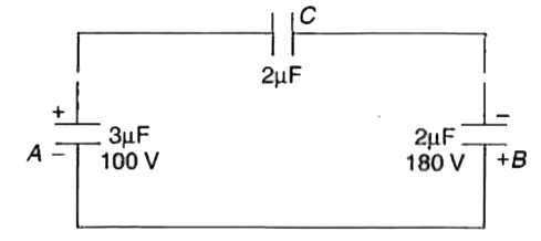
(a) तीनो संधारित्रों पर अंतिम आवेश तथा
(b) परिपथ पूर्ण होने के पहले तथा बाद में, निकाय में संचित स्थिरवैगहट स्थितिज ऊर्जा का परिणाम|
View SolutionC1 धारिता के एक संधारित्र को V विभव से आवेशित किया जाता है तथा फिर C2 धारिता के एक अनावेशित संधारित्र से समान्तर क्रम में जोड़ा जाता है। प्रत्येक संधारित्र में अंतिम विभवान्तर होगा-
View SolutionA capacitor of capacitance C_1 is charged to a potential V_1 , while another capacitor of capacitance C_2 is charged to a potential difference V_2 . The capacitors are now disconnected from their respective charging batteries and connected in parallel to each other Find the total energy stored in the two capacitors before they are connected .
View SolutionTwo capacitors of 2μFand3μF are charged to 150 volt and 120 volt respectively. The plates of capacitor are connected as shown in the figure. A discharged capacitor of capacity 1.5μF fails to the free ends of the wire. Then
View SolutionThree uncharged capacitors of capacities C_1 ,C_2 and C_3 are connected as shown in the figure to one another and the point. A, B and C are at potentials V_1,V_2, and V_3 , respectively. Then the potential at will be
View Solutionदो संधारित्र A एवं B जिसकी धारिता 3μF एवं 2μF को क्रमशः 100 V एवं 180 V के बैटरी से आवेशित किया गया। संधारित्र के प्लेट को चित्रानुसार एक तार से एक दूसरे से जोड़ा गया कि प्रत्येक संधारित्र का एक तार स्वतंत्र है। A का ऊपरी प्लेट धनात्मक एवं B का ऋणात्मक है। एक अनआवेशित 2μF संधारित्र C लोड तार के साथ स्वतंत्र सिरे पर गिरता है जिससे के परिपथ पूरा हो जाता है ज्ञात करे।
(i) प्रत्येक संधारित्र पर अंतिम आवेश
(ii) निकाय में संचित विद्युत स्थैतिक ऊर्जा परिपथ के पूर्ण होने से पहले एवं बाद में

View Solution

