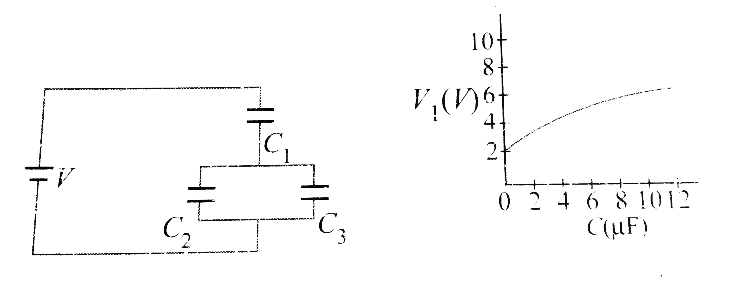
Capacitor C3 in the circuit is a variable capacitor (its capacitance can be varied). C1andC2 are of fixed values. Graph is plotted between potential difference V1 (across capacitor C1) versus C3. Electric potential V1 approches on asymptote of 10 V as C3∝∞.
 ,
,
The electric potential V across the battery is equal to
10V
12V
16V
20V
The correct Answer is:B
When C3→∞ it means distance between the plates of C3 is zero or both plates will be at the same potential then C2 will be shorted entire pontential V will ber across C1 hence V=V1=10V
From graphs when C3=0,V1=2V.SoC3 will act like open switch C1 and C2 will be in series potential different across C2 is V2=10−V1
=8V
q=C1V1=C2V2 or C12=C28 or C1=4C2
V1=4V,V2=10−4=6V
q=C1V1=(C2+C3)V2
or C14=(C2+C3)6 or 16C2=6C2+6C3
or C3=5C2/3
Similar Questions
C1 धारिता के एक संधारित्र को V विभव से आवेशित किया जाता है तथा फिर C2 धारिता के एक अनावेशित संधारित्र से समान्तर क्रम में जोड़ा जाता है। प्रत्येक संधारित्र में अंतिम विभवान्तर होगा-
View SolutionWhen two capacitors C_1 and C_3 are connected in series, the ratio of charges and potential differences across two capacitors are _________ and __________ respectively.
View SolutionThree identical capacitors C_1 , C_2 and C_3 of capacitance 6 mu F each are connected to a 12 V battery as shown in Fig charge on each capacitor
View SolutionCalculate the potential difference and the energy stored in the capacitor C_2 in the circuit shown in the Fig. Given potential at A is 90 V , C_1 = 20 mu F , C_2 = 30 mu F and C_3 = 15 mu F
View SolutionIn the series combination of three capacitors of capacitances C_1, C_2, C_3, the equivalent capacitance will be
View SolutionThree uncharged capacitors of capacitance C_1,C_2 and C_3 are connected to one another as shown in figure. The potential at O will be
View SolutionA capacitor of capacitance C1 is charged up to potential V and then connected in parallel to an uncharged capacitor of capcitance C2 The final potential difference across each capacitor will be-
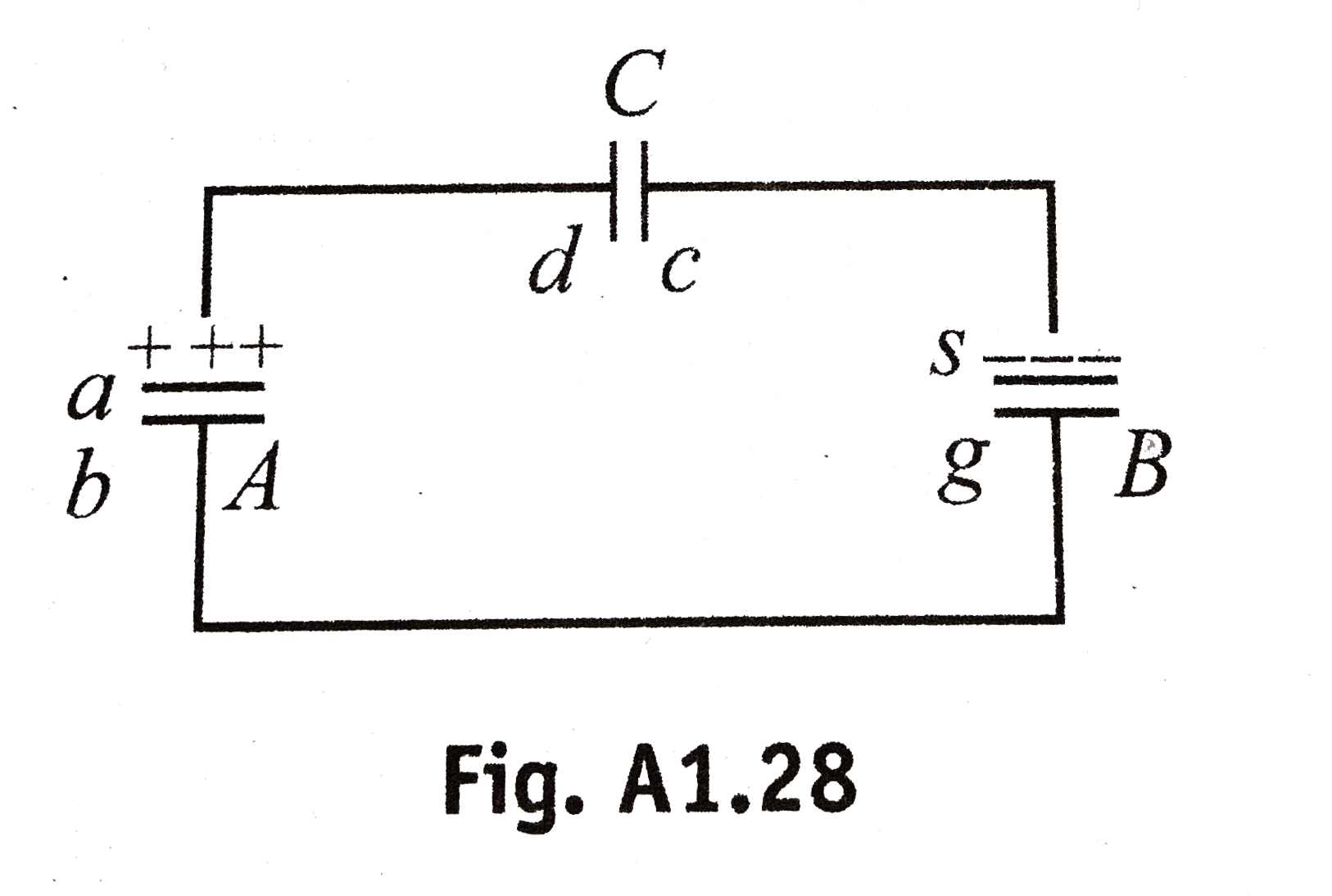
View SolutionTwo capacitors A and B with capacities C1andC2 are charged to potential difference of V1andV2 respectively. The plates of the capacitors are connected as shown in the figure with one wire free from each capacitor. The upper plate of A is positive and that of B is negative. An uncharged capacitor of capacitance C3 and lead wires falls on the free ends to complete circuit, then

View Solution

