Two vertical conducting rails separted by distance 1.0m are placed parallel to z-axis as shown in figure. At z=0, a capacitor of 0.15F is connected between the rails and a metal rod of mass 100g placed across the rails slides down along the rails. if a constant magnetic fields of 2.0 T exists perpendicular to the plane of the rails, what is the acceleration of the rod?
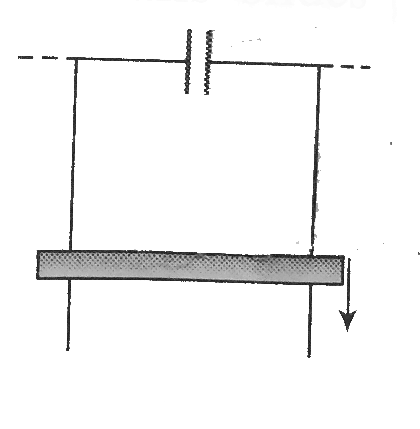
2.5m/s2
zero
9.8m/s2)
1.4m/s2)
The correct Answer is:D
Motional emf induced across capacitor, e=Blv
:. Charge trored in capacitor, Q=Ce=C(Blv)
current in the rod I=dQdt=CBldvdt=Cbla
force oppoosing the downward motion, Fm=Bll
Fm=B(Cbla)l=B2l2Ca
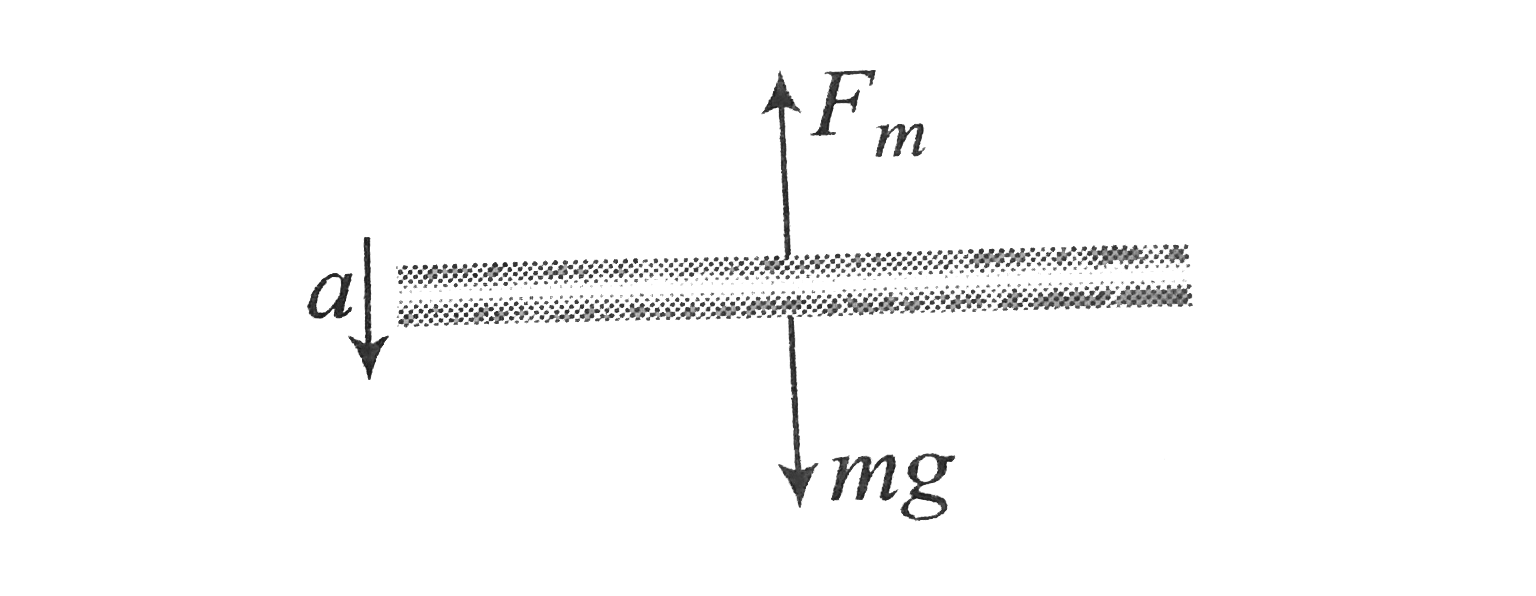
From FBD of rod
ma=mg−B2l2Ca
or a=mg(m+B2l2C)
so, a=0.1×9.8(0.1+22×12×0.15)=1.4m/s2
Similar Questions
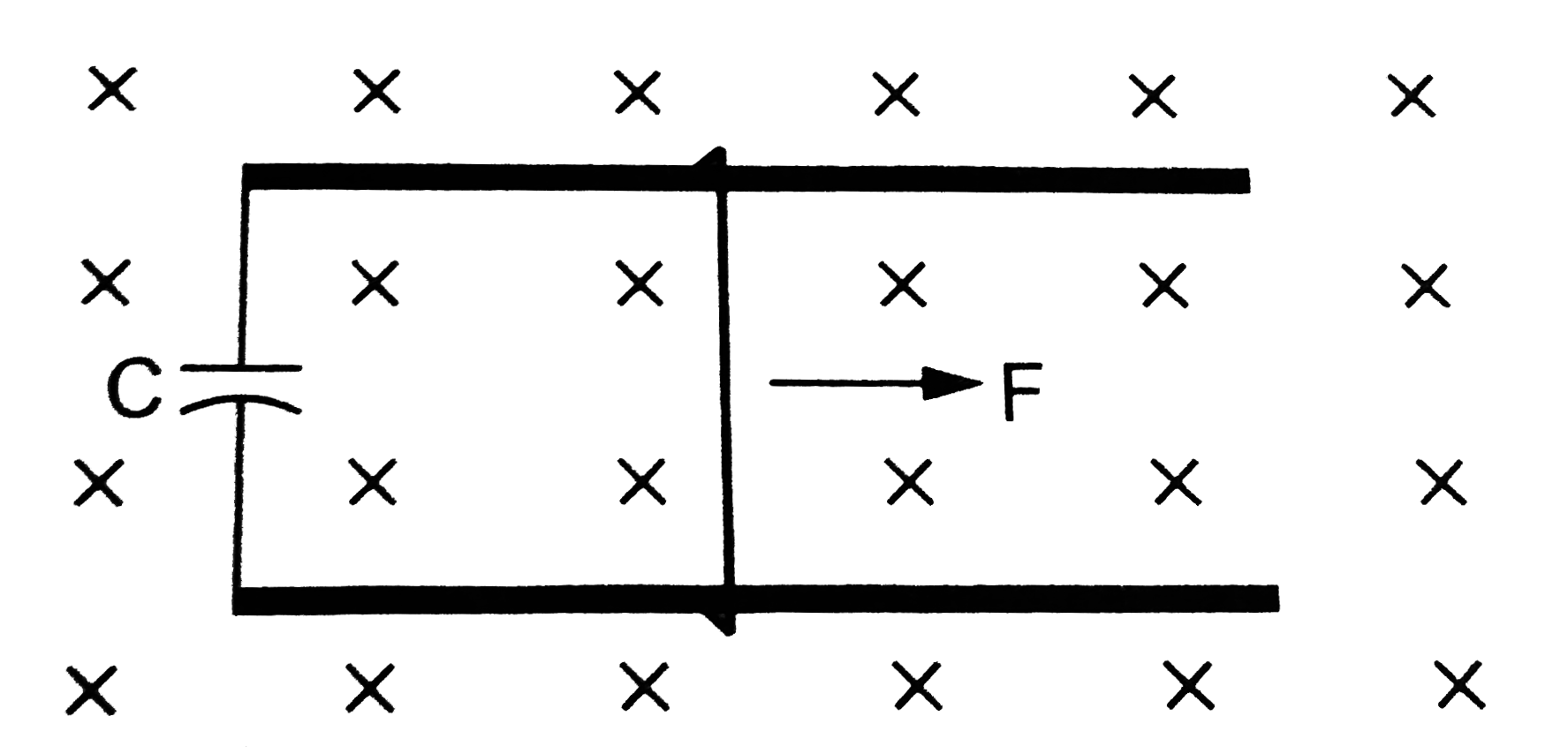
A wire of mass m and length I can freely slide on a pair of parallel, smooth, horizontal rails placed in a vertical magnetic field B . The rails are connected by a capacitor of capacitance C. The electric resistance of the rails and the wire is zero. If a constant force F acts on the wire as shown in the figure, find the acceleration of the wire.
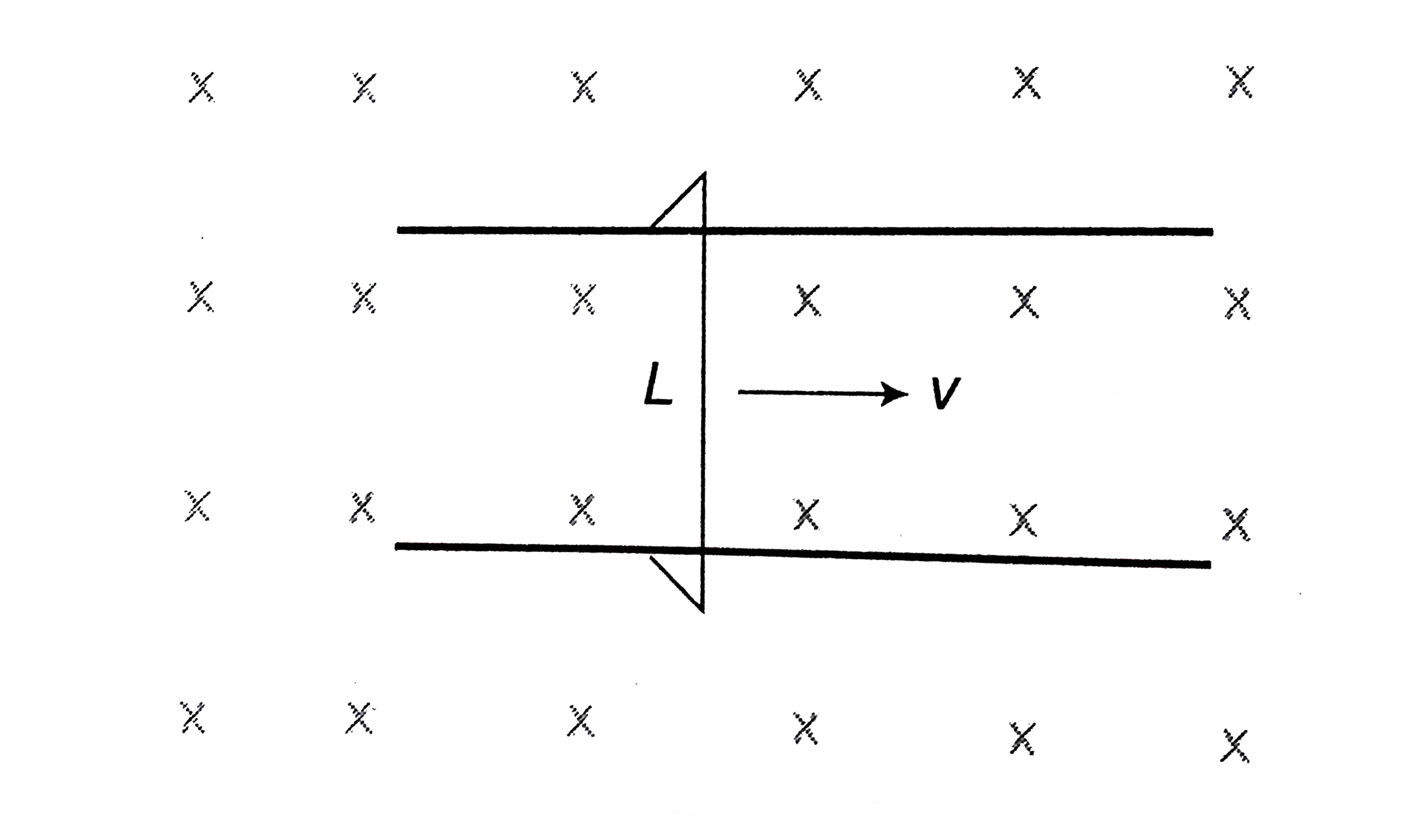
View SolutionFigure shows a wire sliding on two parallel, conducting rails placed at a separation L . A magnetic field B exists in a direction perpendicular to the plane of the rails. What force is necessary to keep the wire moving at a constant velocity V ?
View SolutionAB and CD are fixed conducting smooth rails placed in a vertical plane and joined by a constant current source at its upper end. PQ is a conducting rod which is free to slide on the rails. A horizontal uniform magnetic field exists in space as shown in figure. If the rod PQ is released from rest then,
View SolutionA conducting rod of length is moved at constant velocity v0 on two parallel, conducting, smooth, fixed rails, that are placed in a uniform constant magnetic field B perpendicular to the plane for the rails as shown in Fig. A resistance R is connected between the two ends of the rails.
Then which of the following is/are correct:

View SolutionA pair of parallel conducting rails lie at right angle to a uniform magnetic field of 2.0T as shown in the fig. two resistor 10Omega and 5Omega are to slide without friction along the rail. The distance between the conducting rails is 0.1m . Then
View SolutionA conducting rod of length is moved at constant velocity v_(0) on two parallel, conducting, smooth, fixed rails, that are placed in a uniform constant magnetic field B perpendicular to the plane for the rails as shown in Fig. A resistance R is connected between the two ends of the rails. Then which of the following is/are correct:
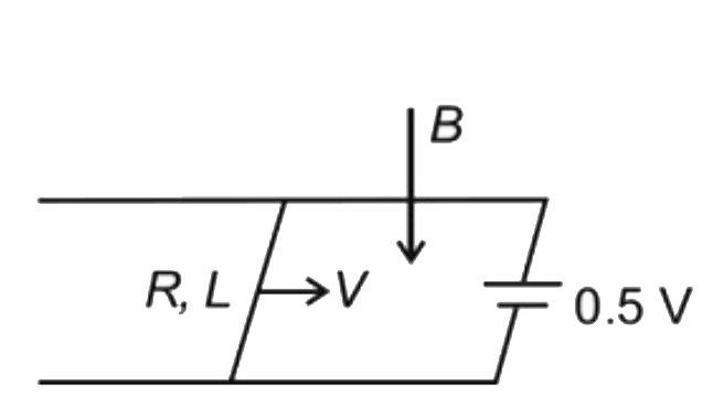
View SolutionThere is a pair of fixed, parallel rails of negligible resistance in a horizontal plane, at a distance of L = 10 cm. The rails are connected, at one of their ends to an ideal battery of EMF 0.5 V, as shown in the figure. The system is placed in a vertically downward and perpendicular magnetic field of magnetic induction B = 1T. A metal rod of resistance R=10Ω is placed perpendicularly on the rails. The rod placed perpendicularly on the rails. The rod and rails are frictionless. The magnitude of force, which is to be exerted on the rod in order to move it with a constant speed of order to move it with a constant speed of 1ms−1 in the direction shown, is
View SolutionA rod of length l and resistance r is shown in the figure, which is moving on two rails connected by resistance R, a uniform magnetic field B is present perpendicular to the plane of the rod and the rail. Show the electrical equivalent of each branch -
View Solution

