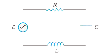
A variable frequency 230 V alternating voltage source is connected across a series combination of L=5.0H,C=80μF and R=40Ω
(i) Calculate the angular frequency fo the source which drives the circuit in resonance.
(ii) Obtain r.m.s. the impedance of the circuit and amplitude of current at resonance frequency
(iii) Obtain r.m.s. potential drop across the three elements of the circuit at resonating frequency.
(iv) How do you explain the observation that the algerbraic sum of voltages across the three elements obtained is greater than the supplied voltage.
To solve the given problem step by step, we will address each part of the question sequentially.
Given Data:
- Inductance, L=5.0H
- Capacitance, C=80μF=80×10−6F
- Resistance, R=40Ω
- Voltage, V=230V
(i) Calculate the angular frequency of the source which drives the circuit in resonance.
At resonance in an RLC circuit, the inductive reactance XL equals the capacitive reactance XC. The formula for angular frequency ω at resonance is given by:
ω=1√LC
Substituting the values:
ω=1√5.0×80×10−6
Calculating LC:
LC=5.0×80×10−6=4.0×10⁻⁴
Now, calculating √LC:
√LC=√4.0×10−4=0.02
Thus,
ω=10.02=50rad/s
(ii) Obtain r.m.s. impedance of the circuit and amplitude of current at resonance frequency.
At resonance, the impedance Z is equal to the resistance R:
Z=R=40Ω
The r.m.s. current Irms can be calculated using Ohm's law:
Irms=VrmsZ
Substituting the values:
Irms=23040=5.75A
(iii) Obtain r.m.s. potential drop across the three elements of the circuit at resonating frequency.
1. Voltage across the resistor VR:
VR=Irms×R=5.75×40=230V
2. Voltage across the inductor VL:
VL=Irms×XL=Irms×ωL
Where XL=ωL=50×5=250Ω
VL=5.75×250=1437.5V
3. Voltage across the capacitor VC:
VC=Irms×XC=Irms×1ωC
Where XC=1ωC=150×80×10−6=250Ω
VC=5.75×250=1437.5V
(iv) Explanation of the observation that the algebraic sum of voltages across the three elements is greater than the supplied voltage.
The voltages across the inductor and capacitor are out of phase by 180 degrees. Therefore, they can be represented as:
VL+VC=1437.5−1437.5=0
The total voltage across the circuit is:
Vtotal=VR+(VL−VC)=230+0=230V
The algebraic sum of the voltages across the inductor and capacitor does not contribute to the total voltage because they cancel each other out. Thus, the observed phenomenon is due to the phase difference between the voltages across the inductor and capacitor.
- Inductance, L=5.0H
- Capacitance, C=80μF=80×10−6F
- Resistance, R=40Ω
- Voltage, V=230V
VR=Irms×R=5.75×40=230V
VL=Irms×XL=Irms×ωL
Where XL=ωL=50×5=250Ω
VL=5.75×250=1437.5V
VC=Irms×XC=Irms×1ωC
Where XC=1ωC=150×80×10−6=250Ω
VC=5.75×250=1437.5V
Similar Questions
एक परिवर्ती आवृति 230 V प्रत्यावर्ती वोल्टेज स्रोत एक श्रेणी LCR परिपथ (जिसमें L = 5H, C=80μF,R=40Ω) से जोड़ दिया जाता है । गणना कीजिए -
(a) परिपथ में अनुनाद के लिए स्रोत कोणीय आवृति
(b) परिपथ की प्रतिबाधा
(c ) अनुनाद की स्थिति में धारा का आयाम
View Solutionएक श्रेणी LCR परिपथ में L=10.0H,C=40μF तथा R=60Omega को 240V वोल्ट के परिवर्ती आवृत्ति के प्रत्यावर्ती धारा स्त्रोत से जोड़ा गया है । गणना कीजिए -(i ) स्त्रोत की कोणीय आवृत्ति जो परिपथ को अनुनाद की अवस्था में लाती है ,(ii ) अनुनादी आवृत्ति पर धारा , (iii ) प्रेरक के सिरों के बीच अनुनाद की दशा में वर्ग - माध्य - मूल विभव पतन ।
View SolutionFigure shows a series LCR circuit connected to a variable frequency 230 V source. L = 5.0 H, C = 80muF, R = 40 Omega . (a) Determine the source frequency which drives the circuit in resonance. (b) Obtain the impedance of the circuit and the amplitude of current at the resonating frequency. (c) Determine the rms potential drops across the three elements of the circuit. Show that the potential drop across the LC combination is zero at the resonating frequency.
View SolutionFigure shows a series LCR circuit connected to a variable frequency 230 V source. L=5.0H,C=80μF,R=40Ω.

(a) Determine the source frequency which drives the circuit in resonance.
(b) Obtain the impedance of the circuit and the amplitude of current at the resonating frequency.
(c) Determine the rms potential drops across the three elements of the circuit. Show that the potential drop across the LC combination is zero at the resonating frequency.
View SolutionFigure shows a series LCR circuit connected to a variable frequency 230 V source. L=5.0H,C=80μF,R=40Ω.

Determine the source frequency which drives the circuit in resonance.
View SolutionFigure shows a series LCR circuit connected to a variable frequency 230 V source. L = 5.0 H, C = 80muF, R = 40 Omega . (a) Determine the source frequency which drives the circuit in resonance. (b) Obtain the impedance of the circuit and the amplitude of current at the resonating frequency. (c) Determine the rms potential drops across the three elements of the circuit. Show that the potential drop across the LC combination is zero at the resonating frequency.
View SolutionA series LCR circuit connected to a variable frequency 230 V source has L = 5.0 H, C = 80 mu F , R = 40 Omega , Fig. (a) Determine the source frequency which drives the circuit in resonance. (b) Obtain the impedance of the circuit and amplitude of current at at resonating frequency. (c ) Determine the r.m.s. potential drops acorss the three elements the circuits. Show that the potential drop acorss the LC combination is zero at the resonating frequecny.
View SolutionA series LCR circuit with L=4.0H,C=100μF and R=60Ω is connected to a variable frequency 240 V source. Calculate
(i) angular frequency of the source which drives the circuit in resonance,
(ii) current at the resonating frequency,
(iii) rms potential drop across the inductance at resonance.
View Solution
