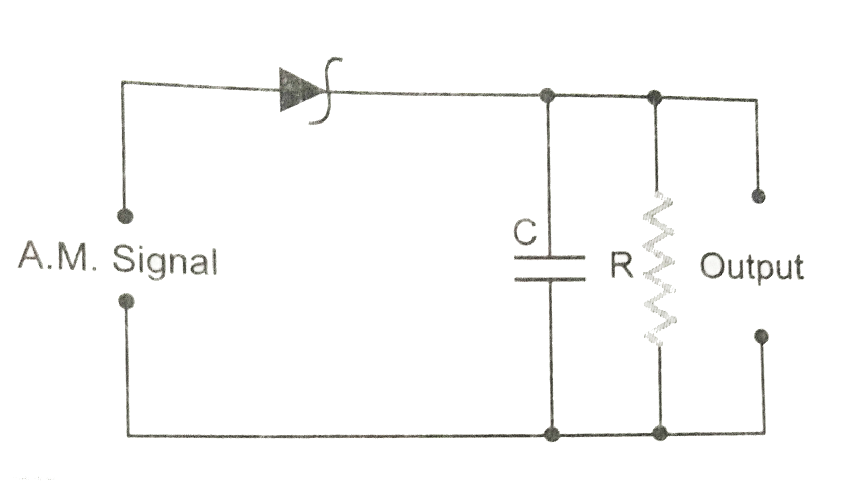
Fig. 10 (CF).1 is the circuit diagram of an AM demondulator. For good demodulation of AM signal of carrier frequency f, the value of RC should be

RC=1/f
RC<1/f
RC≤1/f
RC>>1/f
For good denodulation, 1f<<RC
or RC>>1f
Similar Questions
200 kHz की वाहक आवृत्ति और 10 kHz के मॉडुलन संकेत के लिए आयाम मॉडुलित (AM ) सिगनल की बैण्ड चौड़ाई होगी:
View SolutionAssertion : FM broadcast is preferred over AM broadcast .
Reason : Process of combining the message signals with carrier wave is called demodulation .
View SolutionFor good demodulation of AM signal of carrier frequency f, the value of RC should be
View Solutionवाहक आवर्ती f के AM संकेत के अच्छे डिमॉडुलताएँ के लिए RC का मान होना चाहिए
View Solutionωm आवृत्ति के एक संदेश सिग्नल को, आयाम माडुलित (AM) तरंग प्राप्त करने के लिए, ωc आवृत्ति की एक वाहक तरंग पर आरोपित (superposed) किया गया है। AM तरंग की आवृत्ति होगी
View SolutionAssertion : FM broadcast is preferred over AM broadcast .
Reason : Process of combining the message signals with carrier wave is called demodulation .
View SolutionA message signal of frequency omega_m is superposed on a carrier wave of frequency omega_c to get an amplitude modulated wave (AM). The frequency of AM wave will be
View Solutionωm आवृत्ति का एक सन्देश सिग्नल को, आयाम मॉडुलन (AM) तरंग प्राप्त करने के लिए, ωc आवृत्ति की एक वाहक तरंग पर अध्यारोपित होता है, तो AM की आवृत्ति होगी
View Solution

