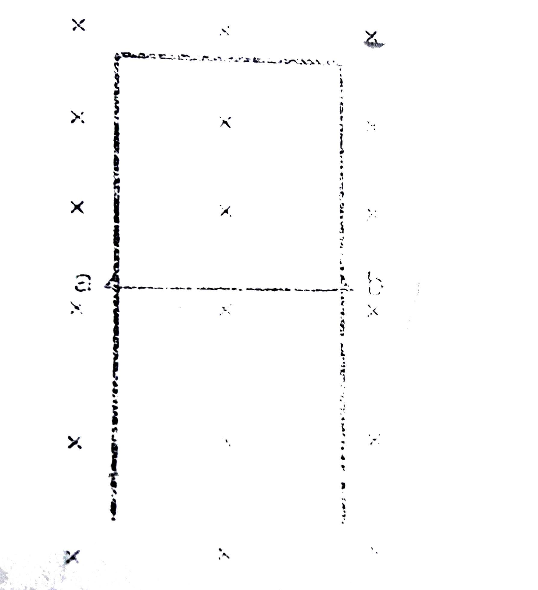
Two straight conducting rails form a right angle where their ands are joined. A conducting bar contanct with the rails starts at vertex at the time t=0 & moves symmetrically with a constant velocity of 5.2m/s to the right as shown in figure. A 0.35T magnetic field point out of the page. Calculate:
(i) The flux through the tringle by the rails & ber at t=3.0s.
(ii) The emf around the tringle at that time.
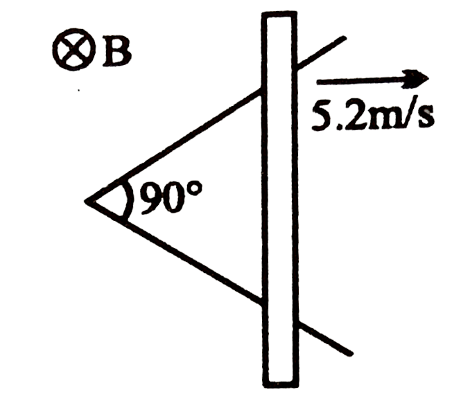
In what manner does the emf around the tringle vary with time.
The correct Answer is:(i)85.22Tm2;(ii)56.8V;(iii)l∈early
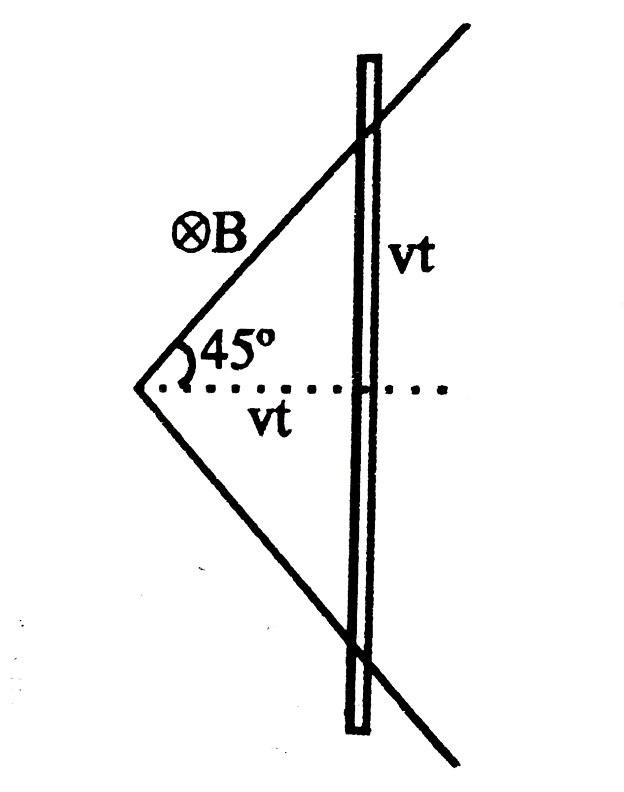
(i)ϕ=BA,=B(12vt×vt)×2=Bv2t2
ϕ=0.35×(5.2)2×(3)2=85.22weber
(ii) e=∣dϕdt)=Bv22t=2Btv2<br>2×0.35×3×(5.2)2=56.8volt
(iii) e=2Bv2t⇒e∝t
Similar Questions
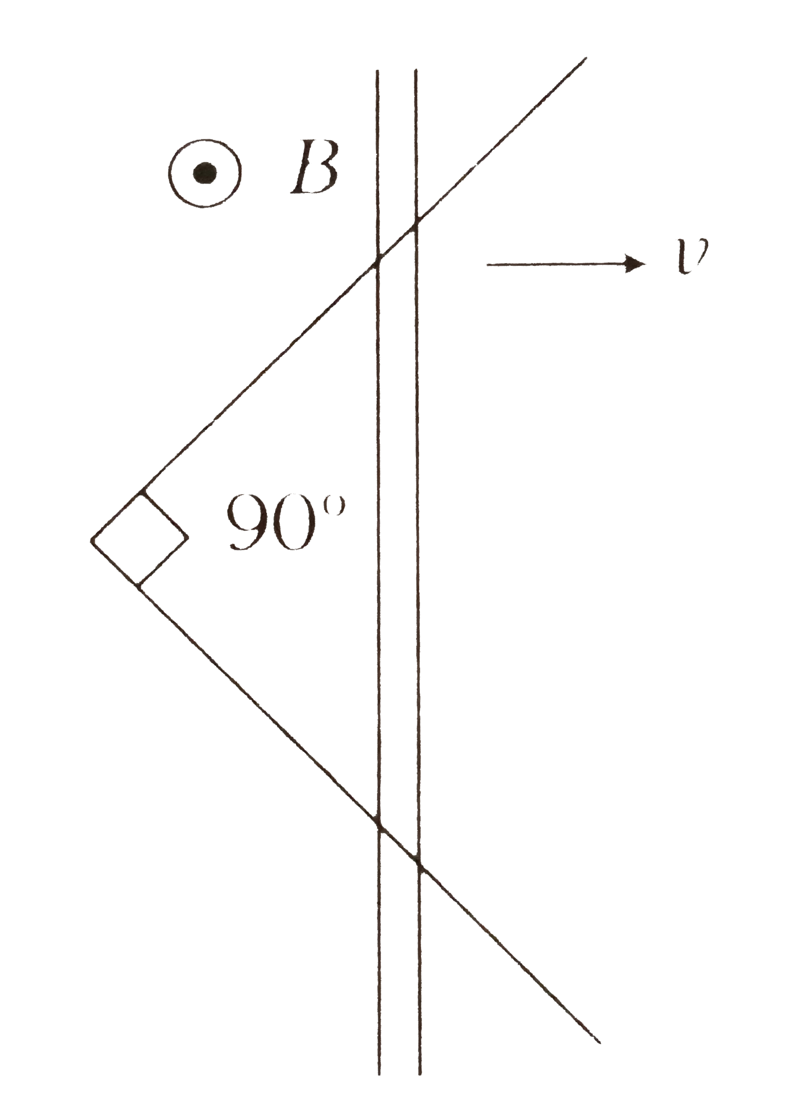
Two straight conducting rails from a right angle where their end are joined. A conducting bar polaced over the rails starts at vertex at the time t=0 and moves with a constant velocity v to the right as shown in the figure. Calculate
(a) the flux through the triangle (isosceles) by the rails and bar at t=t0
the emf around the triangle at that time
(c) in what manner does the emf around the triangle vary with time
View SolutionThe two conducting rails are placed perpendicular to each other, such that their ends are joined as shown in figure. A conducting bar is now placed over the rails and start moving with constant velocity v starting from the vertex at time t = 0.
(i) The flux through the triangle (isosceles) by the rails and bar at t=t0.
(ii) The emf around the triangle at that time.
(iii) In what manner does the emf around the triangle vary with time.
View Solution
Knowledge Check
Two straight conducting rails form a right angle where their ends are joined. A conducting bar in contact with the rails starts at the vertex at time t = 0 and moves with constant velocity v along them as shown in Fig. A magnetic field →B is directed into the page. the induced emf in the circuit at any time t is proportional to
 At∘BtCvoltage across L is equal to zero.Dv2
A copper wire ab of length l, resistance r and mass m start sliding at t=0 down a smooth, vertical, thick pair of connected conducting rails as shown in figure. A uniform magnetic field B exists in the space in a direction perpendicular to the plane of the rails which options are correct .
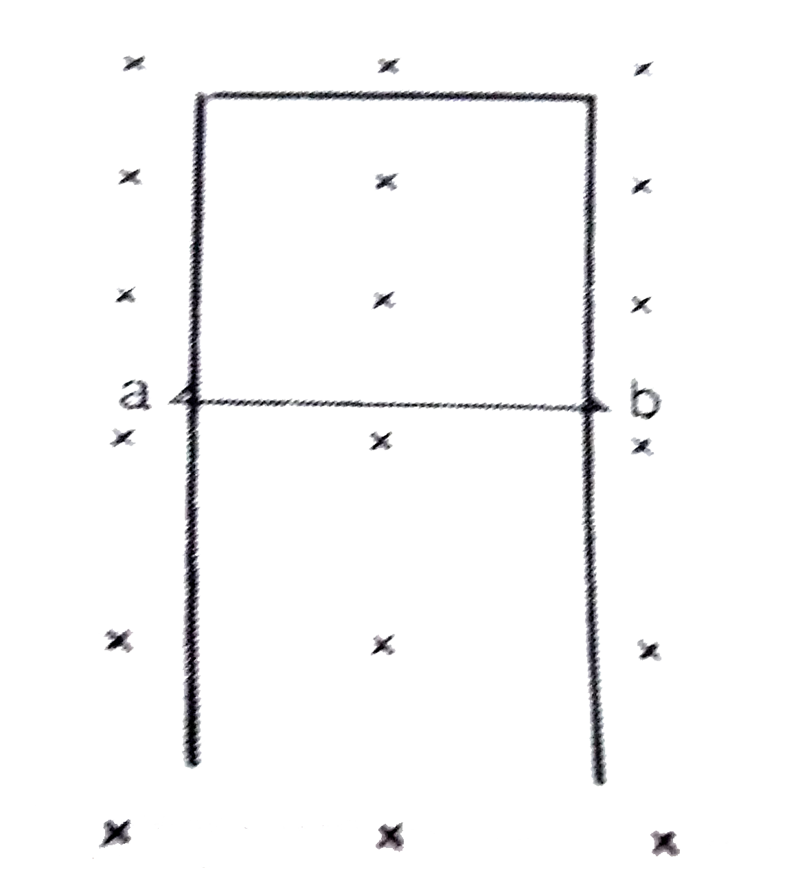 AThe magnitude and direction of the induced current in the wire when speed of the wire v is vBlr, a to bBThe downward acceleration of the wire at this instant g−B2l2mrvCThe velocity of the wire as a function of time vm(1−e−gt/vm),(wherevm=mgrB2l2)DThe displacement of the wire as a function of time vmt−v2mg(1−e−gt/vm),(wherevm=mgrB2l2)
A copper wire ab of length l, resistance r and mass m starts sliding at t=0 down a smooth, vertical, thick pair of connected condcuting rails as shown in figure.A uniform magnetic field B exists in the space in a direction perpendicular to the plane of the rails which options are correct.
 AThe magnitude and direction of the induced current in the wire when speed of the wire v is vBlr, a to bBThe downward acceleration of the wire at this instant g−B2l2mrv.CThe velocity of the wire as a function of time vm(1−e−gt/vm)(where vm=mgrB2l2)DThe displacement of the wire as a function of time vmt−v2mg(1−e−gt/vm)(where vm=mgrB2l2)
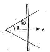
A conducting bar of sufficient length is pulled with a constant velocity in a conducting shaped rail as shown in the figure . Inward magnetic field of induction B is present inside the area bounded by the bar & the rail. Find the external power delivered in moving the rail with constant velocity v at time t ( A= area of cross section of the bar ρ= resistivity of the bar )
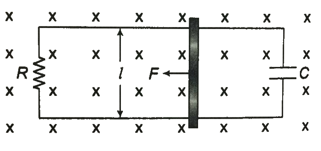
View SolutionTwo parallel long smooth conducting rails separated by a distance l are connected by a movable conducting connector of mass m. Terminals of the rails are connected by the resistor R and the capacitor C as shown in figure. A uniform magnetic field B perpendicular to the plane of the rail is switched on. The connector is dragged by a constant force F. Find the speed of the connector as a function of time if the force F is applied at t=0. Also find the terminal velocity of the connector.
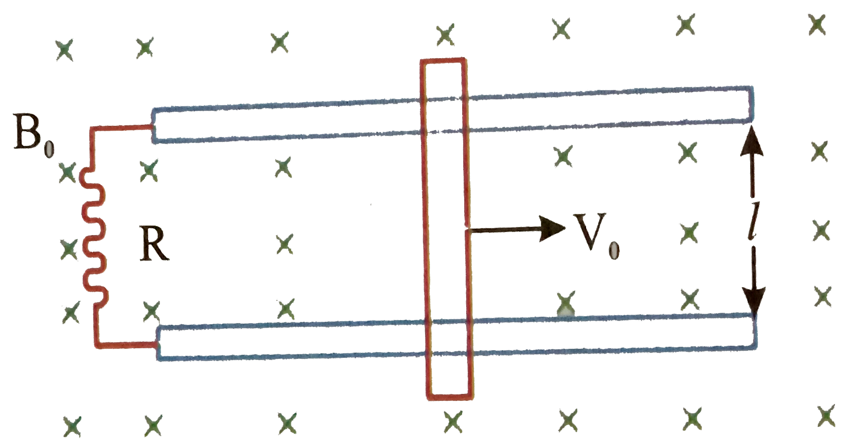
View SolutionA conducting bar mass m and length l moves on two frictionless parallel conducting rails in the presence of a uniform magnetic field B0 directed into the paper. The bar is given an initial velocity v0 to the right and is released at t=0. The velocity of the bar as a function of time is given by
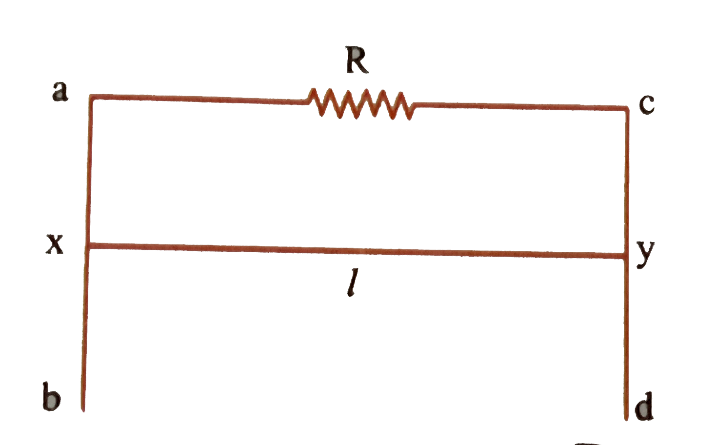
View SolutionA conducting wire xy of lentgh l and mass m is sliding without friction on vertical conduction rails ab and cd as shown in figure. A uniform magnetic field B exists perpendicular to the plane of the rails, x moves with a constant velocity of
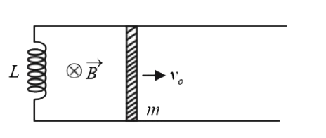
View SolutionAs shown in figure, the two parallel conducting rails, in a horizontal plane, are connected at one end by an inductor of inductance L. A slider (metallic) of mass m, is imparted a Velocity v0, upon the rails, as shown in figure. The period of oscillation of the conducting rod is
View Solution

