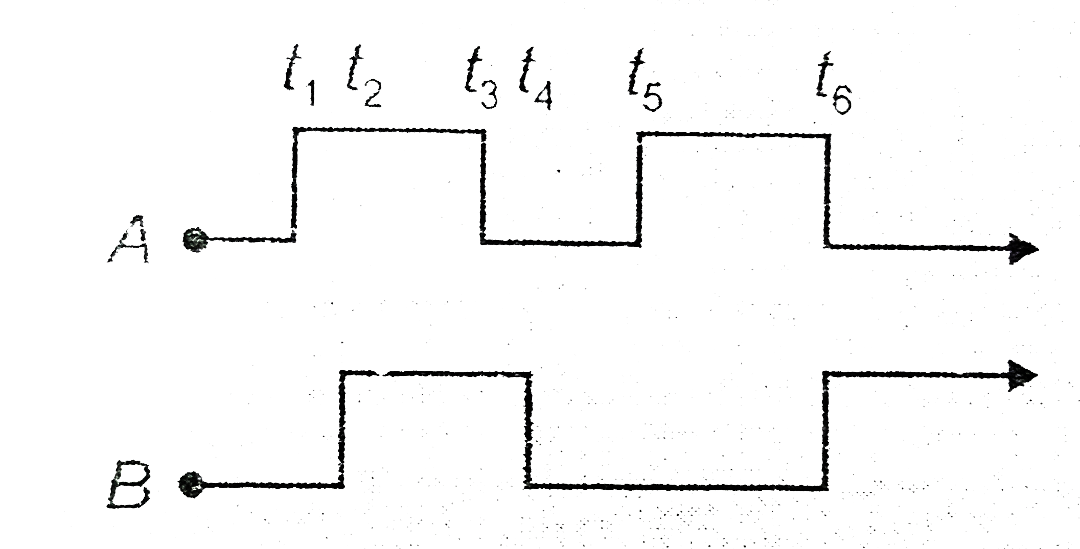
The figure shows input waveforms A and B to a logic gate. Draw the output waveform for an OR gate. Write the truth table for this logic and draw its logic symbol.

The logic symbol and truth table for an OR gate is given below,

Topper's Solved these Questions
- DIGITAL CIRCUITS Book:CHHAYA PUBLICATIONChapter:DIGITAL CIRCUITS Exercise:EXAMINATION ARCHIVE WITH SOLUTIONS (NEET)
Explore 3 Videos
- DIFFRACTION AND POLARISATION OF LIGHTBook:CHHAYA PUBLICATIONChapter:DIFFRACTION AND POLARISATION OF LIGHTExercise:CBSE SCANNER
Explore 27 Videos
- ELECTRIC ENERGY AND POWERBook:CHHAYA PUBLICATIONChapter:ELECTRIC ENERGY AND POWERExercise:CBSE SCANNER
Explore 7 Videos
Similar Questions
The Fig shown input waveforms A and B to a logic gate. Draw the output waveform for an OR gate. Write the truth table for this logic gate and draw its logic symbol.
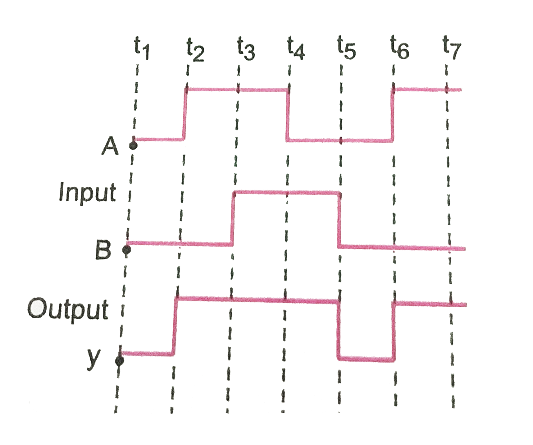
View SolutionThe Fig shown input waveforms A and B to a logic gate. Draw the output waveform for an OR gate. Write the truth table for this logic gate and draw its logic symbol.

View SolutionThe figure shows the input weveforms A and B for 'AND' gate Draw the output waveform and write the truth table for this logic gate
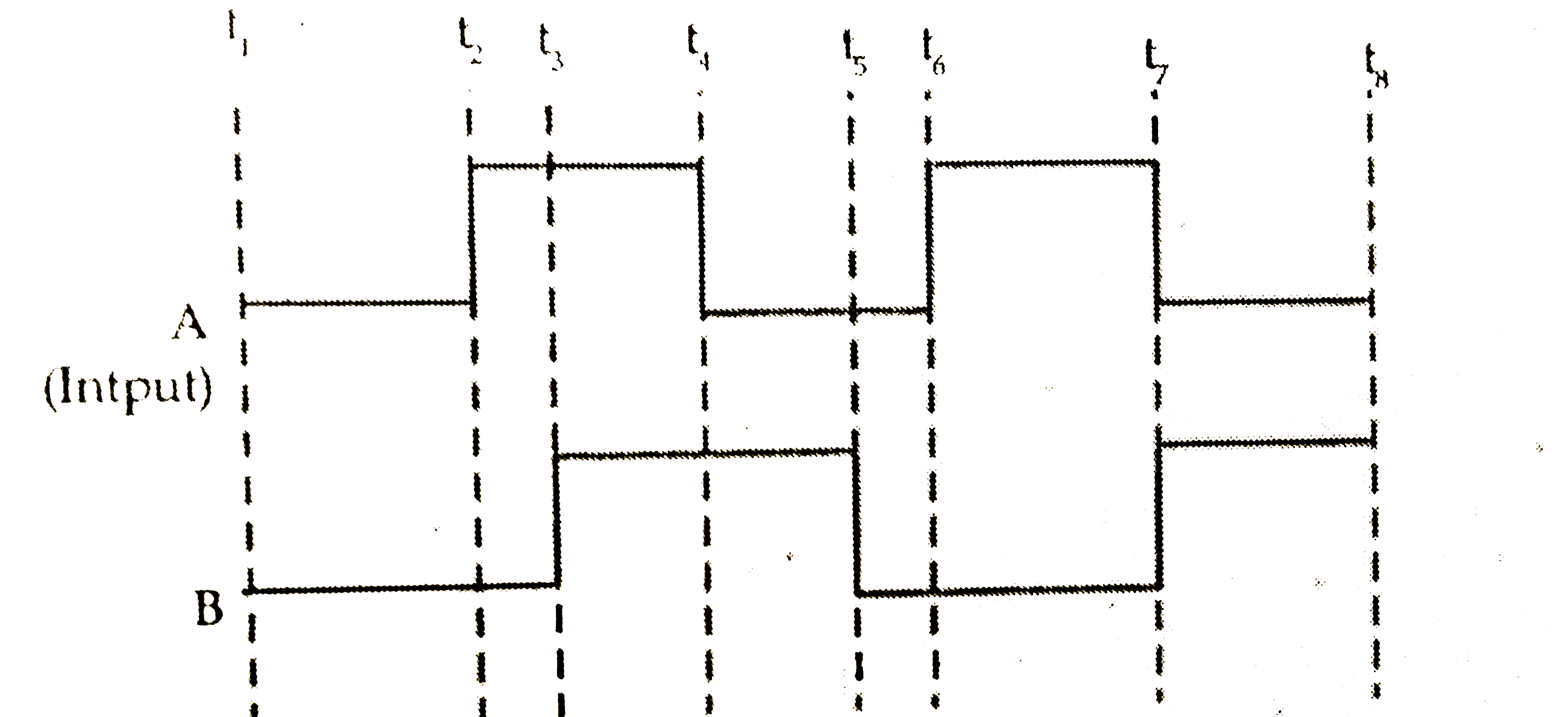 .
.
View SolutionThe Fig.shows the input wavwforms A and B for 'AND' gate. Draw the output waveform and write the truth table for this logic gate.
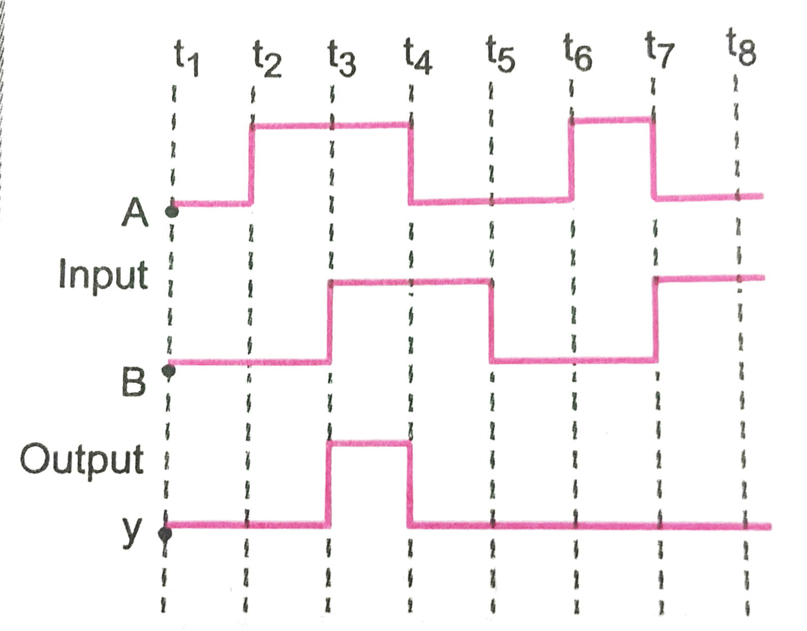
View SolutionWrite the output waveform of the OR gate for the inputs
View SolutionShow the output waveform of OR gate for the following input waveforms of A and B
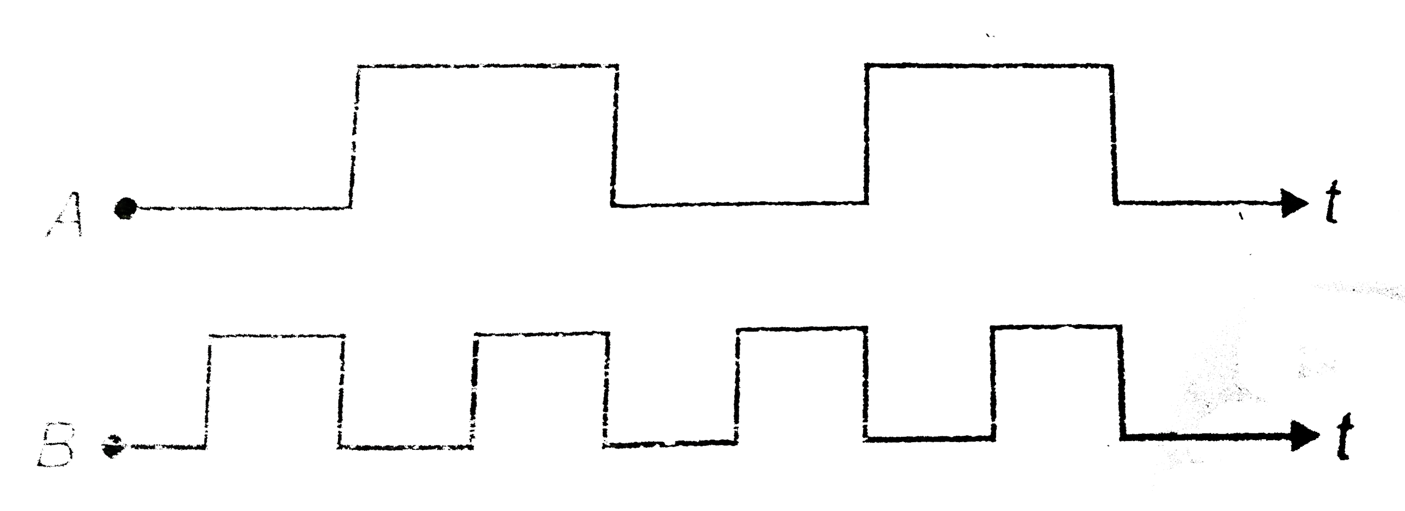
View SolutionShow the output waveform of OR gate for the following input waveforms of A and B
View SolutionThe following Fig. shows the input waveforms (A,B) and the output waveform (y) of a gate. Identify the gate and write its truth table.
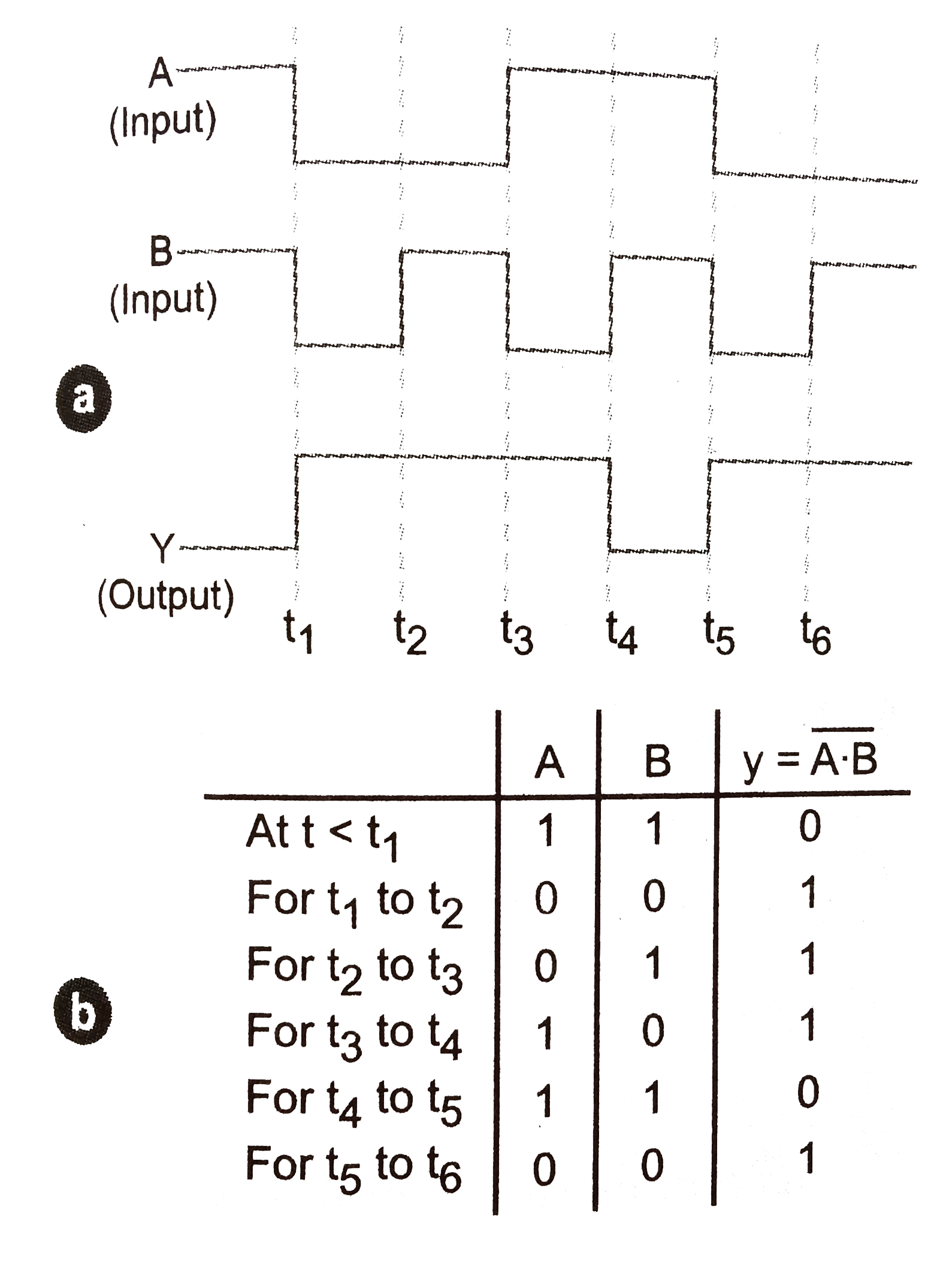
View SolutionThe following Fig. shows the input waveforms (A,B) and the output waveform (y) of a gate. Identify the gate and write its truth table.

View Solutionshow the output waveform of AND gate for the following input waveforms of A and B.

View Solution

