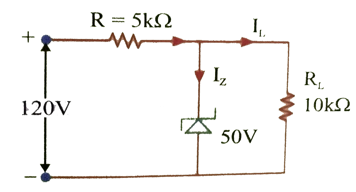
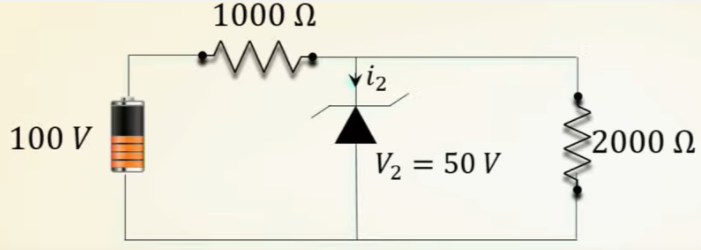
For the circuit shown in figure, Find
(1) the output voltage ,
(2) the voltage drop across series resistance ,
(3) the current through Zener diode.
 .
.
Video Solution
Text Solution
From the figure R=5kΩ=5×10³Ω ,
input voltage Vin=12V , zener voltage, Vz=50V
(1) Output voltage Vz=50V
(2) Voltage drop across series resistance R=Vin−Vz=120−50=70V
(3) Load current IL=VzRL=5010×103=5×10⁻³A
Current through R=i=Vin−VzR
=705×103=14×10−3A
According to Kirchoff's first law I=IL+Iz
∴ Zener current
Iz=I−IL=14×10−3−5×10−3=9×10−3=9mA.
|
Similar Questions
From the zener diode circuit shown in the figure, find (1) the output voltage (2) the voltage drop across series resistance and (3) the current through zener diode.
View Solution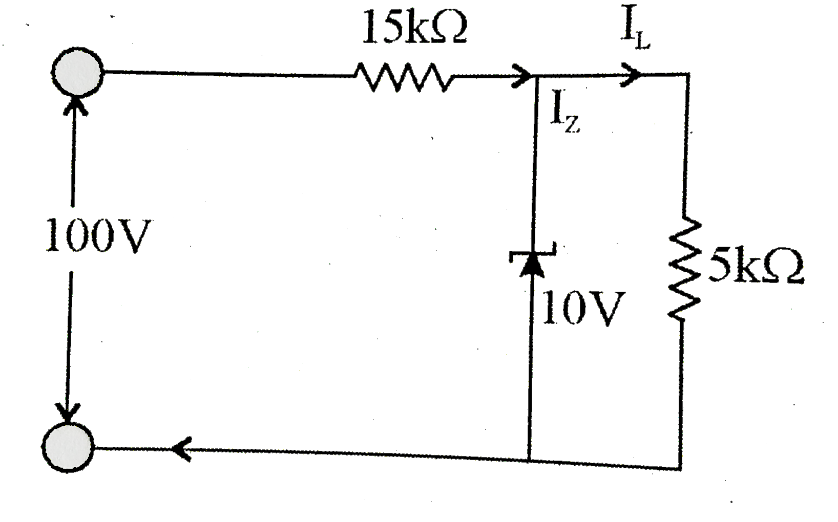
for the circuit shown in figure, find
(i). The output voltage
(ii). The votlage drop across series resistance
(iii). The current through zener diode.
View Solution
Knowledge Check
In the circuit shown in figure the maximum output voltage V0 is
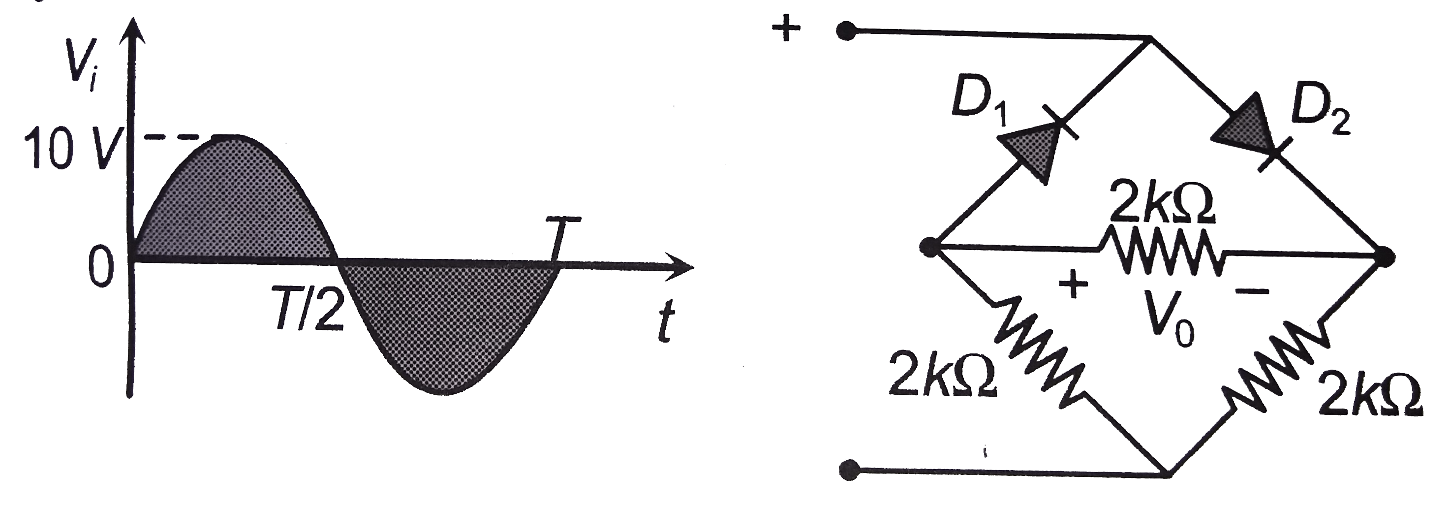 A0VB5VC10VD5√2V
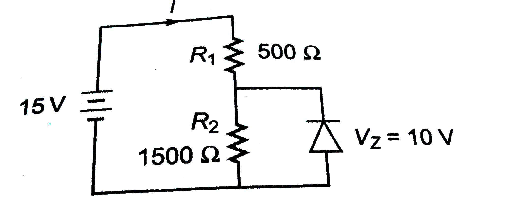
In the circuit given, the current through the Zener diode is
 A10 mAB6.67 mAC5 mAD3.33 mA
For the circuit shown in figure, determine the unknown voltage drop V1.
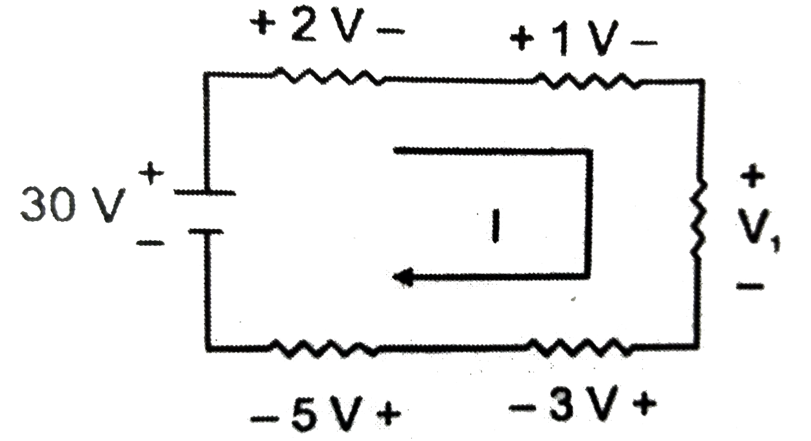
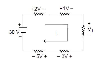
View SolutionFor the circuit shown in figure , determine the unknown voltage drop V1.
View Solution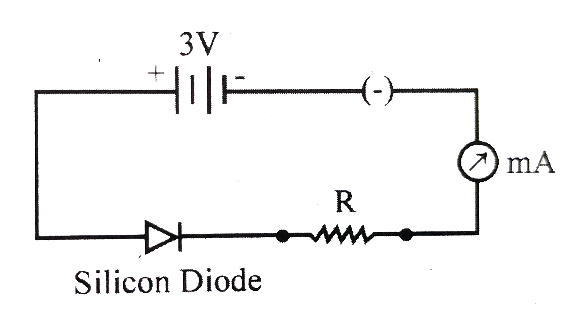
In the above circuit, the voltage drop across the resistance (R) is
View SolutionIn the given circuit, the current through zener diode is :
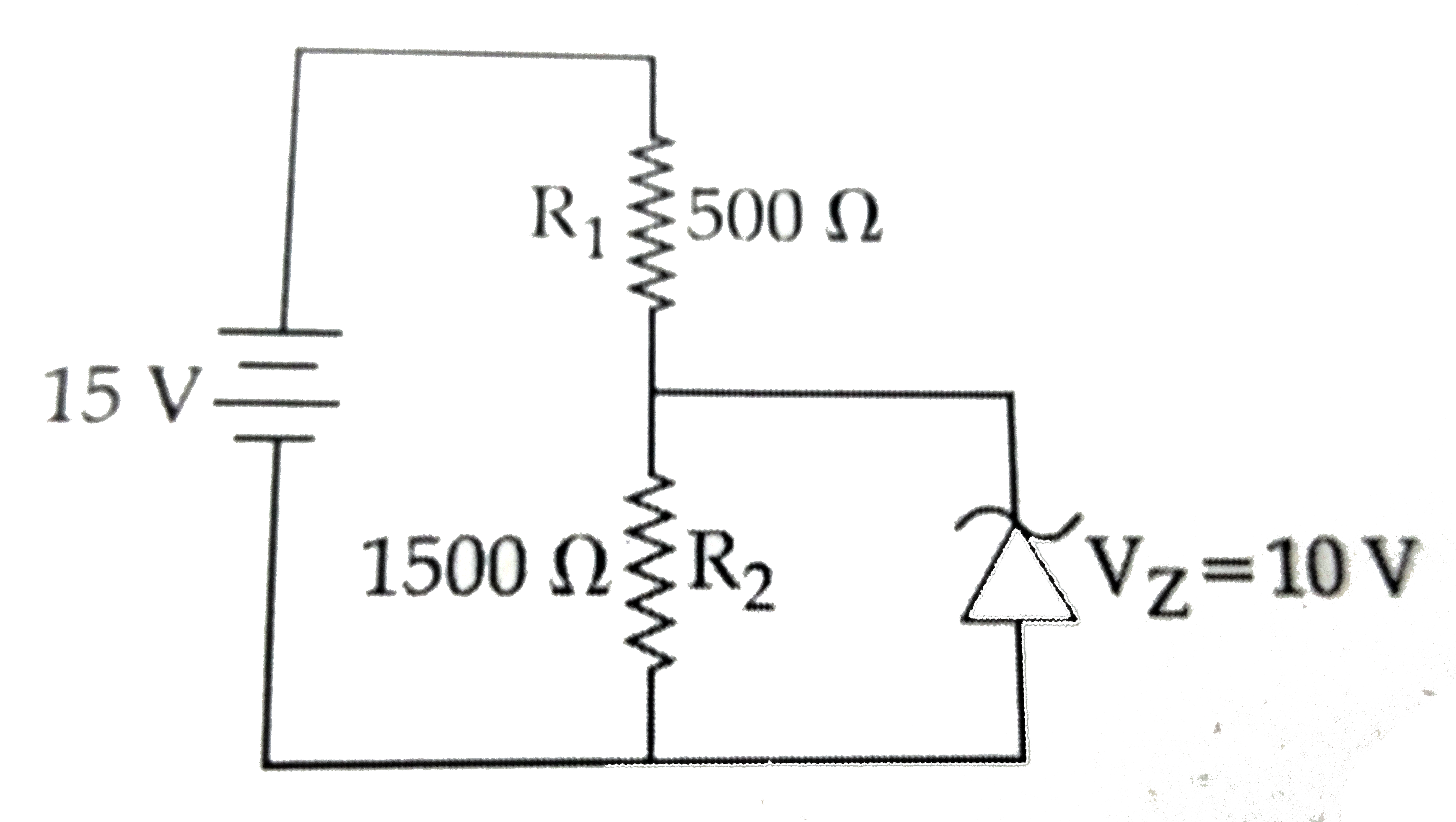
View SolutionIn the circuit shown,find the current through the Zener diode.
View SolutionIn the circuit given the current through the Zener diode is
View Solution

