In the circuit shown there is steady state with the switch closed. The switch is opened at t=0 Choose the correct option(s) (Given varepsilon=24V,C_(1)=3Fand C_(2)=2F)
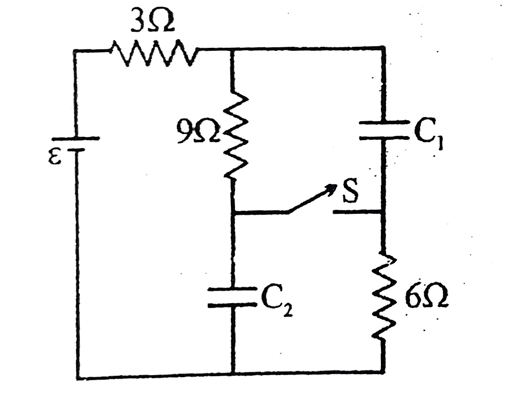
The voltage across C1 before the switch is open is 12V
The voltage across C1 after a long time after the switch is open is 12V
The voltage across C2 after a long time after the switch is open is 24V
The voltage across C2 before the switch is open is 8V
The correct Answer is:A, C, D
i=243+9+6=43A
V1=43×9=12
V2=43×6=8V
at t=∞
V,=V1=24
Similar Questions
Knowledge Check
In the given circuit Fig the switch is closed at t=0. Choose the correct answers.
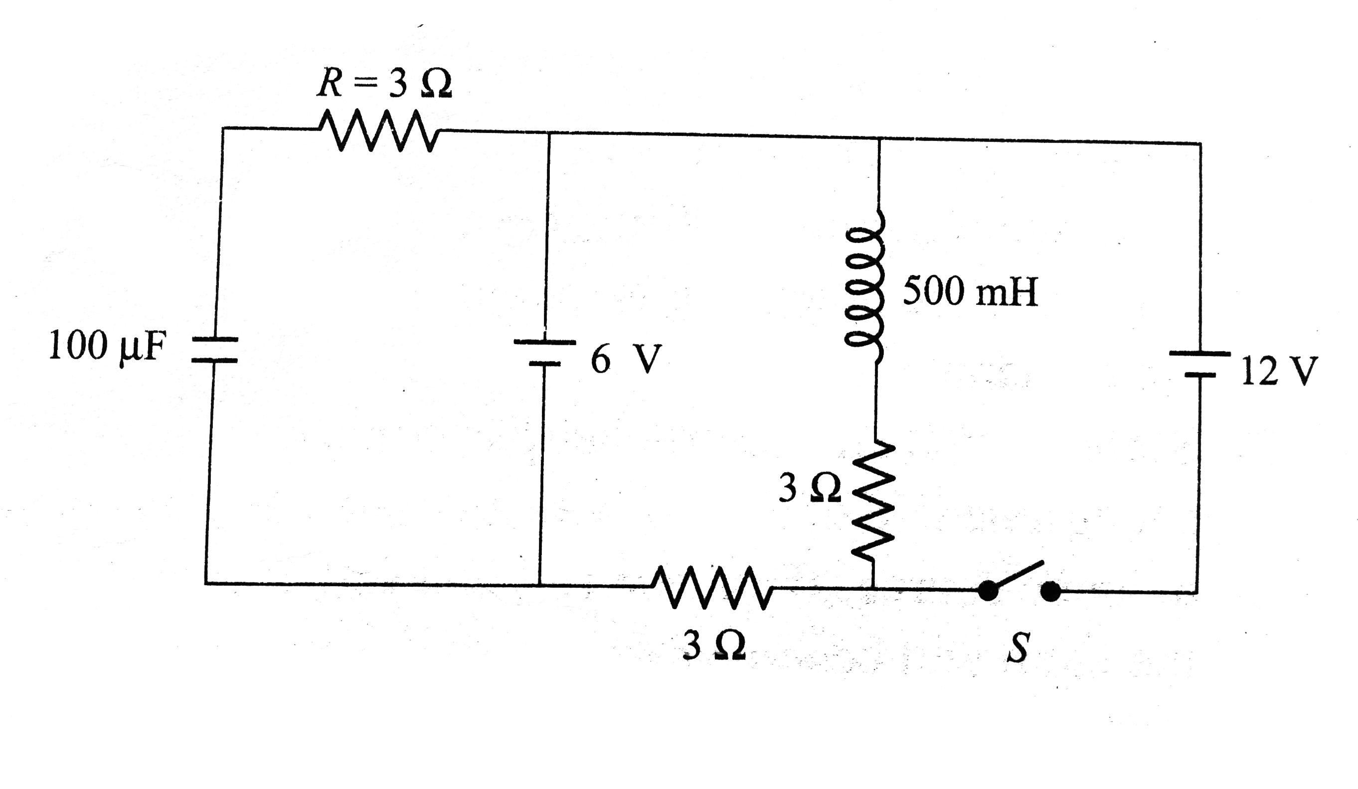 ACurrent in the inductor when the circuit reaches the steady state is 4A.BThe net change in flux in the inductor is 1.5Wb.CThe time constant of the circuit after closing S is 555.55sDThe charge stored in the capacitor in steady state is 1.2mC.
In the circuit shown, the reading of ammeter when switch S is open and when switch S is closed respectively are
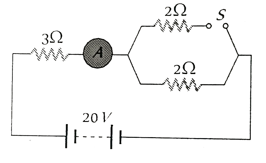 A3A and 4AB4A and 5AC5A and 6AD6A and 7A
The circuit consists of two resistors (of resistance R1=20Ω and R2=10Ω), a capacitor (of capacitance C=10μF) and two ideal cells. In the circuit shown the capacitor is in steady state and the switch S is open
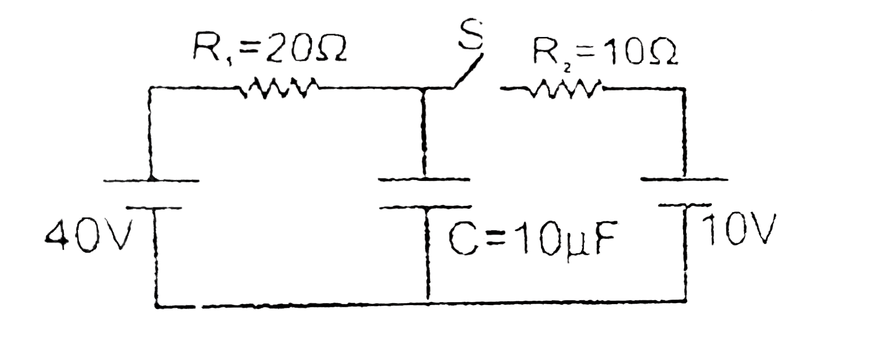
the circuit is in steady state with switch S closed. Now the switch S is opened. Just after the switch S is opened. the current through resistance R1 isA1 ampereB2 ampereC3 ampereD4 ampere
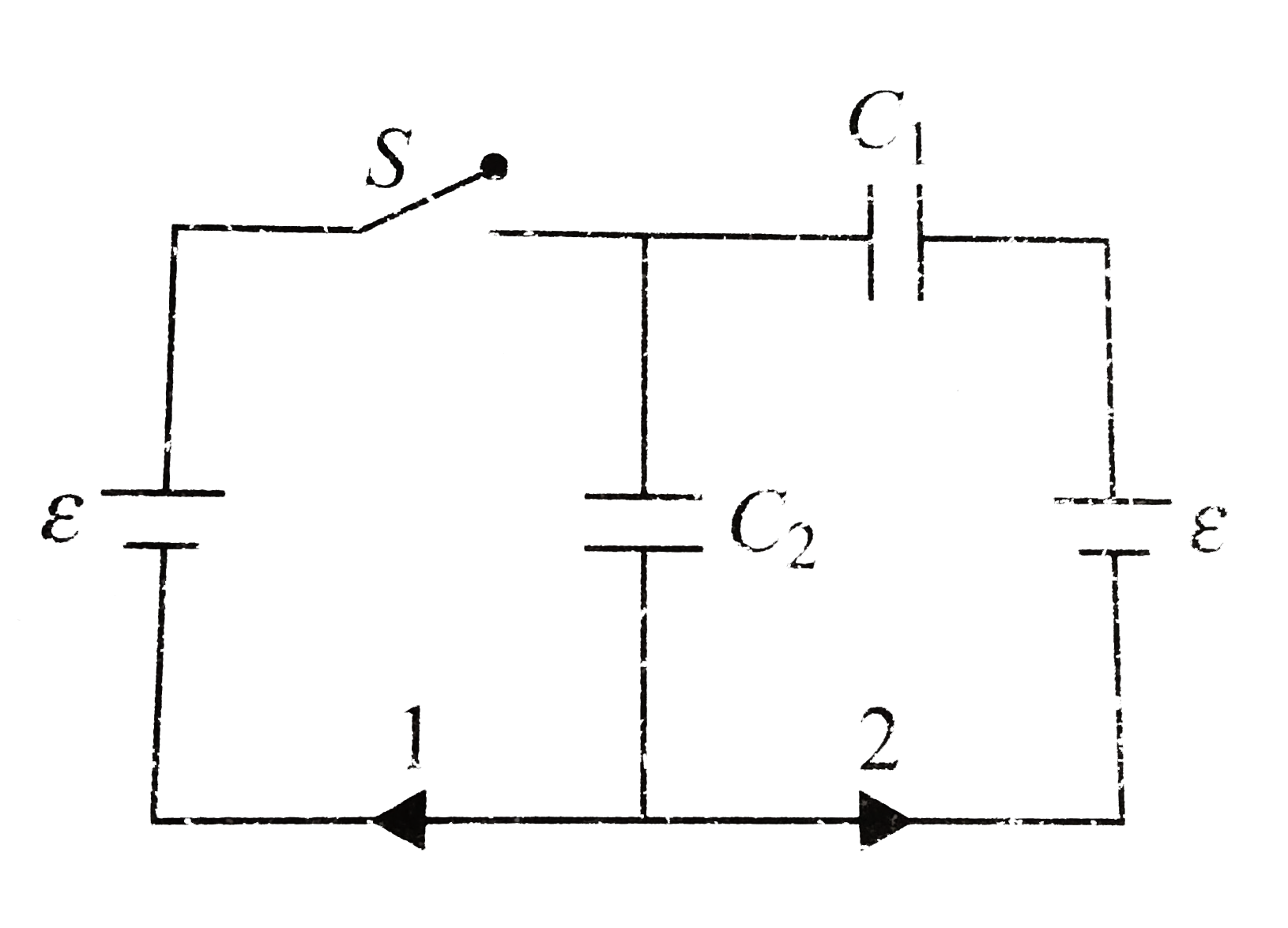
In the circuit shown in figure initially the switch is opened. The switch is closed now.
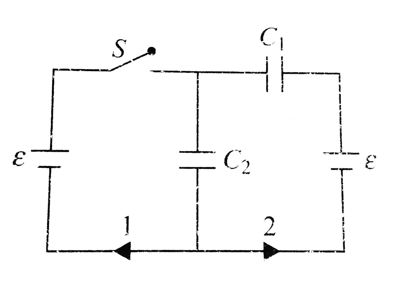
The charge that will flow in direction 1 is
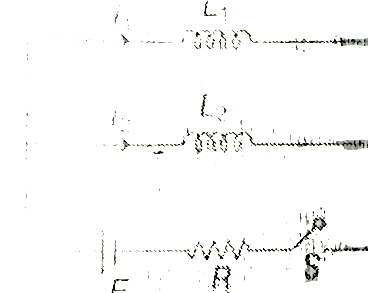
View SolutionIn the circuit shown in the figure The steady state currents i1andi2 in the coils after the switch S is closed are
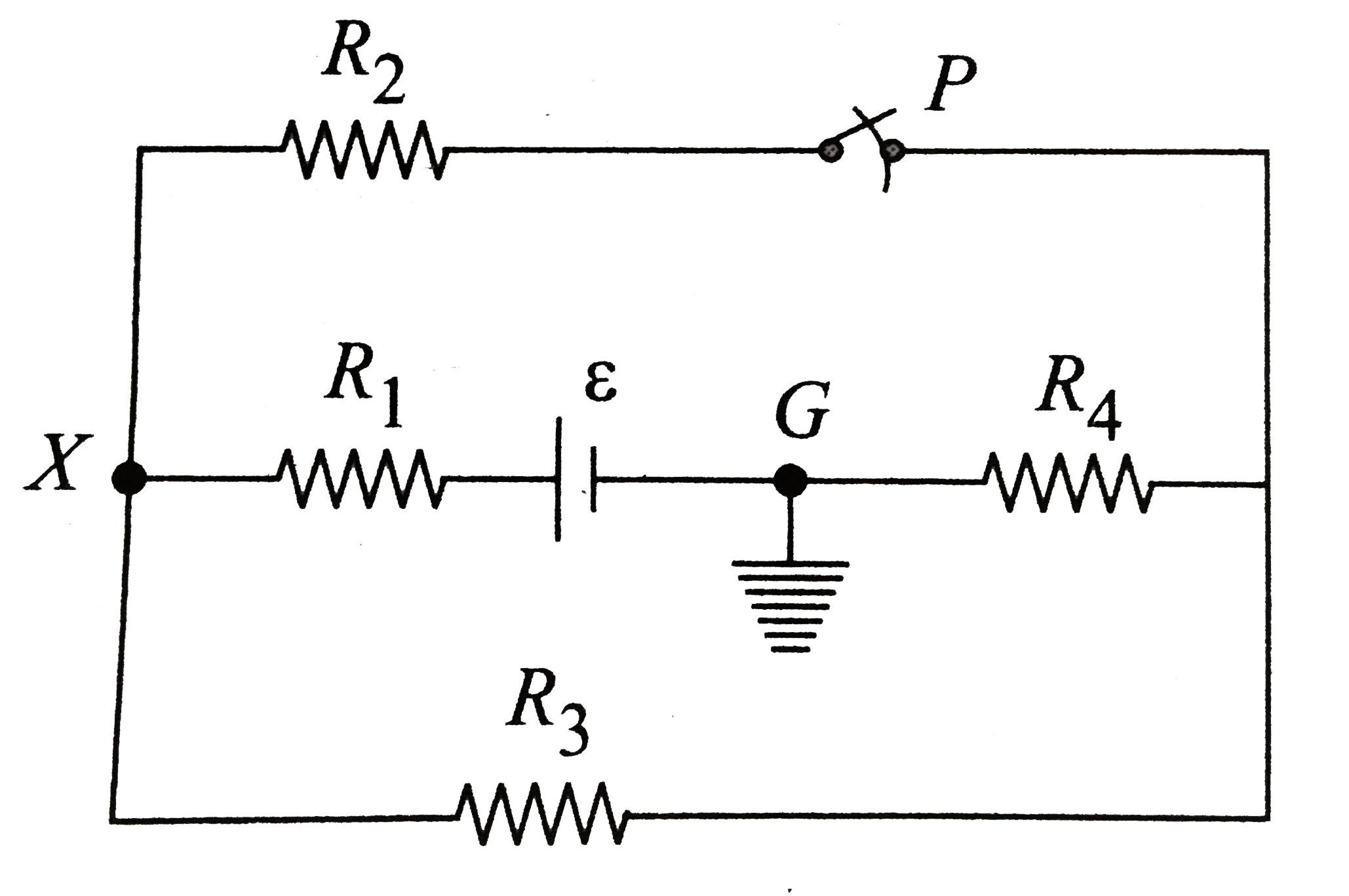
View SolutionIf the switch at point P is opened (which was initially closed), choose the correct option (s).
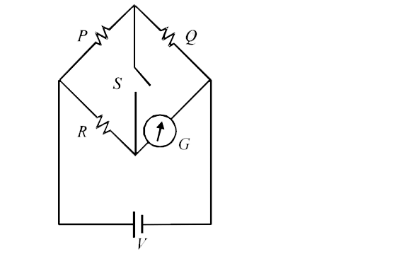
View SolutionIn the circuit P≠R, the reading of the galvanometer is same with switch S open or closed. Then
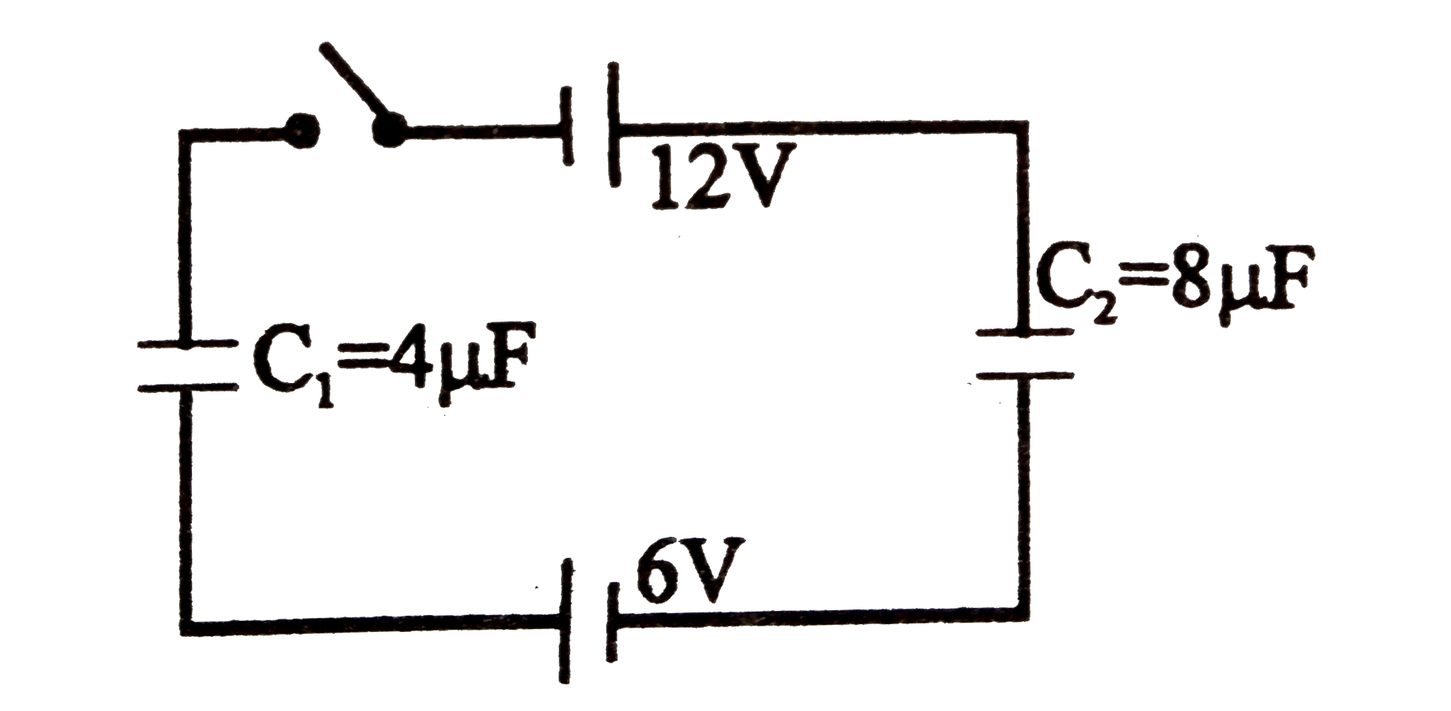
View SolutionIn the circuit shown initially C1,C2 are uncharged. After closing the switch
View Solution

