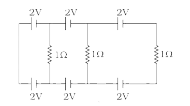
In the given circuit the current in each resistance is

1A
0.25A
0.5A
zero
The correct Answer is:D
Each loop contains two cells of equal and opposite emf . So the net emf in each loop is zero and hence the current in each resistance is zero.
Topper's Solved these Questions
- KIRCHHOFF'S LAWS AND ELECTRICAL MEASUREMENT BOOK - CHHAYA PUBLICATIONCHAPTER - KIRCHHOFF'S LAWS AND ELECTRICAL MEASUREMENT EXERCISE - EXAMINATION ARCHIVE (AIPMT )
4 Videos
- KIRCHHOFF'S LAWS AND ELECTRICAL MEASUREMENT BOOK - CHHAYA PUBLICATIONCHAPTER - KIRCHHOFF'S LAWS AND ELECTRICAL MEASUREMENT EXERCISE - EXAMINATION ARCHIVE (NEET)
1 Video
- KIRCHHOFF'S LAWS AND ELECTRICAL MEASUREMENT BOOK - CHHAYA PUBLICATIONCHAPTER - KIRCHHOFF'S LAWS AND ELECTRICAL MEASUREMENT EXERCISE - EXAMINATION ARCHIVE (WBJEE )
5 Videos
- ELEMENTARY PHENOMENA OF ELECTROSTATICS BOOK - CHHAYA PUBLICATIONCHAPTER - ELEMENTARY PHENOMENA OF ELECTROSTATICS EXERCISE - EXAMINATION ARCHIVE
2 Videos
- LIGHT WAVE AND INTERFERENCE OF LIGHT BOOK - CHHAYA PUBLICATIONCHAPTER - LIGHT WAVE AND INTERFERENCE OF LIGHT EXERCISE - CBSE SCANNER
15 Videos
Similar Questions
Circuit has been set up for finding the internal resistance of a given cell . The main battery used across the potentimeter wire itself is 4 m long . When the resistance R , connected across the given cell ,ha =s values of (i) infinity , (ii) 9.5Ω the balancing lengths on the potentiometer wire are found to be 3 cm and 2.85 m respectively . The value of internal resistance of the cell is
View SolutionA poterntimeter wire is 100 cm long and a constant potential difference is maintained acrooss it . Two cells are connected in seires first to support one another and then in opposite direction . The balance points are obtained at 50 cm and 10 cm from the positive end the wire in the two cases . The ratio of emf's is
View SolutionThe current I in the circuit shown is

View SolutionDefine surface density of electric charge
View SolutionIn Young's double slit experiment derive the condition for (i) constructive interference and (ii) destructive interference at a point on the screen.
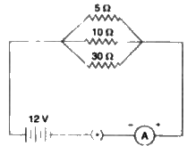
View SolutionIn the circuit diagram given in (Fig. 3.57), calculate : (a) the current through each resistor (b) the total current in the circuit ( c) the total effective resistance of the circuit. .
View SolutionIn the following circuit the current in each resistance is
View SolutionIn the given circuit diagram if each resistance is of 10 Omega , then the current in arm AD will be
View Solution
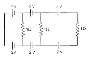
In the given circuit, the current in each resistance is:
View SolutionIf an ideal diode is used in the given circuit, find the current through each resistance
View SolutionIn the above circuit the current in each resistance is -
View SolutionIn the above circuit the current in each resistance is -
View SolutionIn the below circuit, the current in each resistance is:

View Solution
ऊपर दिए गए परिपथ में प्रत्येक प्रतिरोध में धारा का मान होगा
View SolutionIn the given circuit the current in each resistance is
View SolutionIn the given circuit diagram, calculate :
(a) the value of current through each resistor
(b) the total current in the circuit
(c) the total effective resistance of the circuit.

View Solution

