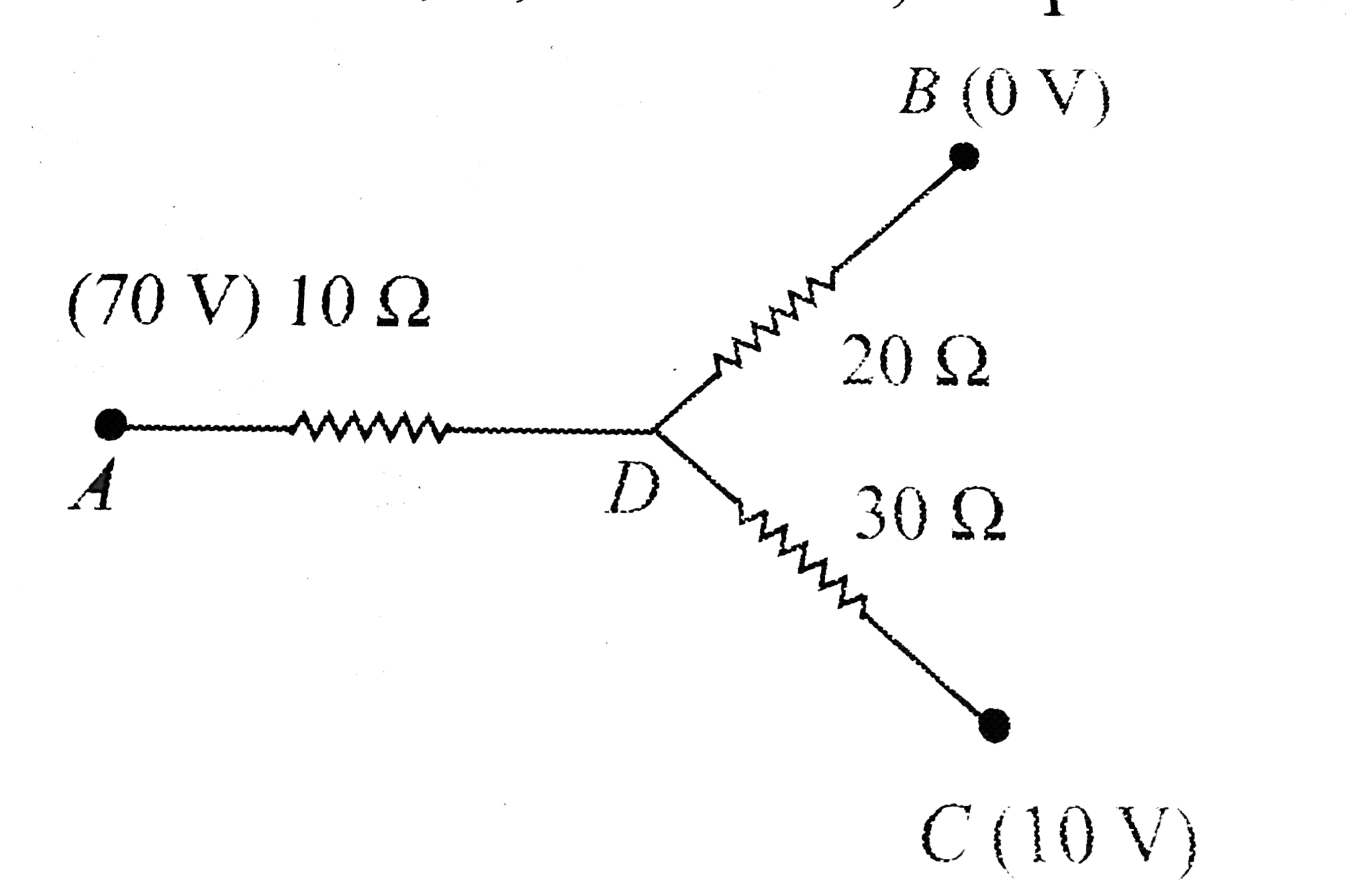
In the network shown in fig. , points A, B, and C are at potentials of 70 V, 0, and 10V, respectively.

Point D is at a potential of 40V.
The currents in the sections AD,DB,DC are int eh ratio 3:2:1
The currents in the sections AD,DB,DC are in the ratio 1:2:3
The network draws a total power of 200W
The correct Answer is:A, B, D
Step by step video, text & image solution for In the network shown in fig. , points A, B, and C are at potentials of 70 V, 0, and 10V, respectively. by Physics experts to help you in doubts & scoring excellent marks in Class 12 exams.
Updated on:21/07/2023Similar Questions
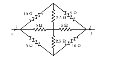
Find the equivalent resistance of the network as shown in Fig 27.48 between points a and b

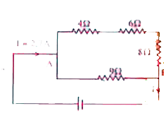
View SolutionFind potential difference between points A and B of the network shown in Fig. and distribution of given main current through different resistors.

View SolutionFind potential difference between points A and B of the network shown in Fig. and distribution of given main current through different resistors.

View SolutionIn the network shown in figure, points A,B and C are at potentials of 70N, 0V and 10V respectively which of the following statements are not true.
View SolutionCalculate the potentials of points A, B,C and D as shown in Fig. a. What would be the new potential values if connections of 6 V battery are reversed as shown in fig b. All resistance are on ohm.
View SolutionIn the network shown in fig. , points A, B, and C are at potentials of 70 V, 0, and 10V, respectively.
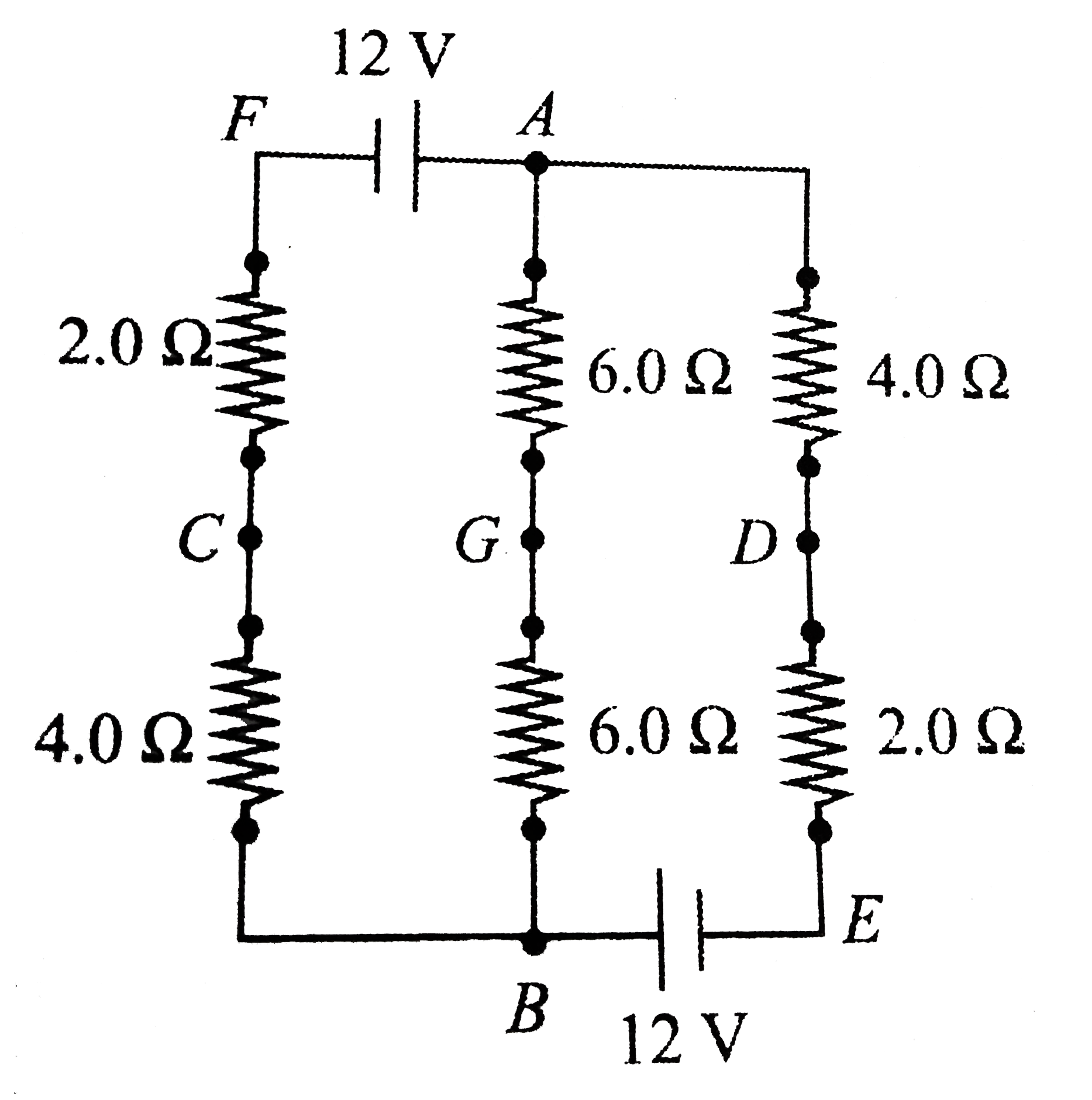
View SolutionIn the network shown in fig. , the potential differene across A and B is

View SolutionCalculate the effective resistance between the points A and B in the network shown below in Fig.

View Solution
