In the figure, an ammeter A and a resistor of resistance R=4Ω have been connected to the terminals of the source to form a complete circuit. The emf of the source is 12V having an internal resistance of 2Ω. Calculate voltmeter and ammeter reading.

Voltmeter reading : 8V, Ammeter reading = 2A
Similar Questions
A cell of emf 1.4V and internal resistance 2Ω is connected in series with a resistance of 100Ω and an ammeter. The resistance of the ammeter is 43Ω.To measure the potential difference between the two ends of the resistance a voltmeter is connected IF the reading of the ammter is 0.02 A.what is the resistance of the voltmeter?
View SolutionA cell of emf 1.4V and internal resistance 2Ω is connected in series with a resistance of 100Ω and an ammeter. The resistance of the ammeter is 43Ω.To measure the potential difference between the two ends of the resistance a voltmeter is connected IF the reading of the voltmeter is 1.10V, what will be its error?
View SolutionA certain circuit with resistance R-100Ω is powered by a direct current source. An ammeter with an internal resistance 1Ω is connected to the circuit to measure the current .What was the current in the circuit before the ammeter was connected if the ammeter shows 5A?
View SolutionA voltmeter of resistance 100 Omega connected to the terminals of a cell reads 2 V. When the voltmeter is replaced by a resistance 1Omega and an ammeter of 1Omega , the ammeter reads 1 A. The EMF of the cell is __________ V.
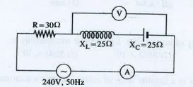
View SolutionIn the circuit shown in the figure, neglecting source resistance, the voltmeter and ammeter readings will respectively be
View Solution(a) The potential difference applied across a given resistor is altered so that the heat produced per second increases by a factor of 9 . By what factor does the applied potential difference change? (b) In the figure shown, an ammeter A and a resistor of 4 Omega are connected to the terminals of the source . The emf of the source is 12V having an internal resistance of 2 Omega . Calculate the voltmeter and ammeter readings.
View SolutionIn the circuit shown in figure neglecting source resistance the voltmeter and ammeter reading will respectively, will be
View SolutionIn the circuit shown in figure
 , neglecting source resistance, the voltmeter and ammeter readings will respectively be
View Solution

