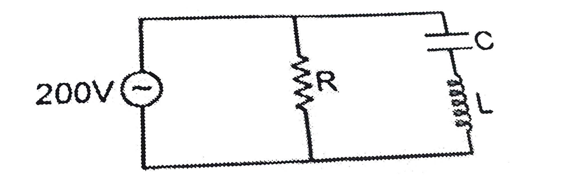
In the circuit diagram show, XC=100Ω,XL=200Ω,&R=100Ω

2A
2√2A
0.5A
√0.4A
In=VR=200100=2A
I'=VXL−XC=200100=2A
I=√12R+I2=2√2Amp

Similar Questions
In a series R, L, C circuit X_(L)=10Omega, X_(c) = 4omega and R = 6Omega . Find the power factor of the circuit
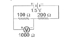
View Solution1.5 वोल्ट का एक आदर्श सेल 100Ω तथा 200Ω के प्रतिरोधों के श्रेणी संयोजन में धारा भेजता है , जैसा की सलगन चित्र में प्रदर्शित है। परिपथ में 100Ω के प्रतिरोध पर या वोल्टता नापने के लिए 1000Ω प्रतिरोध का वोल्टमीटर चित्रानुसार लगा दिया जाता है। वोल्टमीटर का पाठ्यांक ज्ञात कीजिए।

View SolutionDraw phasor diagram for XC>XL and XC<XL and give the disadvantages of this method.
View Solution(A): At resonance power factor of L-C-R series circuit is unity.
(R) : At resonance XC=XL
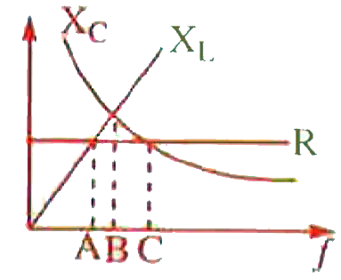
View SolutionThe figure shows variation of R, XL and XC with frequency f in a series L, C, R circuit. Then for what frequency point, the circuit is inductive?

View SolutionIn the circuit diagram show, XC=100Ω,XL=200Ω,&R=100Ω

View SolutionAssertion: At resonance, power factor of L-C-R series circuit is 1. Reason: At resonance, X_(C) = X_(L)
View SolutionIn an L-C-R series circuit R = 10Ω,XL=8Ωand XC=6Ωthe total impedance of the circuit is -
View Solution

