Passage I
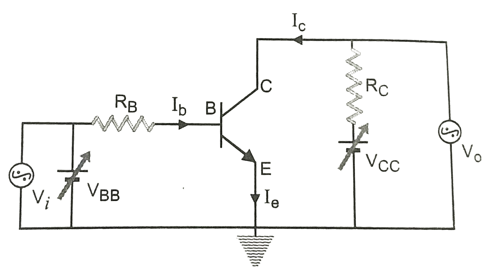
An n-p-n transistor is used as a voltage amplifier in a commoin emitter circuit given
VC=8VIC=4mA
VCE=4V,
(VBE=0.6V,VBB=8V
βDc=200
The value of load resistqacne is
10 k ω
1 k ω
5 k ω
2.5 k ω
To find the value of the load resistance RL in the given n-p-n transistor circuit, we can follow these steps:
1. Identify the Given Values:
- VCC=8V
- IC=4mA=4×10⁻³A
- VCE=4V
- VBE=0.6V
- VBB=8V
- βDC=200
2. Apply Kirchhoff's Voltage Law (KVL):
In a common emitter configuration, we can apply KVL around the collector circuit. The equation can be expressed as:
VC=ILRL+VCE
Here, VC is the voltage at the collector, IL is the load current, and RL is the load resistance.
3. Rearranging the Equation:
We can rearrange the KVL equation to solve for RL:
RL=VC−VCEIL
4. Substituting Known Values:
We know that VC is equal to VCC in this case, so:
RL=VCC−VCEIC
Substituting the known values:
RL=8V−4V4×10−3A
5. Calculating RL:
RL=4V4×10−3A=44×10−3=1000Ω
6. Final Result:
Therefore, the load resistance RL is:
RL=1000Ω=1kΩ
Conclusion:
The value of the load resistance RL is 1kΩ.
---
- VCC=8V
- IC=4mA=4×10⁻³A
- VCE=4V
- VBE=0.6V
- VBB=8V
- βDC=200
In a common emitter configuration, we can apply KVL around the collector circuit. The equation can be expressed as:
VC=ILRL+VCE
Here, VC is the voltage at the collector, IL is the load current, and RL is the load resistance.
We can rearrange the KVL equation to solve for RL:
RL=VC−VCEIL
We know that VC is equal to VCC in this case, so:
RL=VCC−VCEIC
Substituting the known values:
RL=8V−4V4×10−3A
RL=4V4×10−3A=44×10−3=1000Ω
Therefore, the load resistance RL is:
RL=1000Ω=1kΩ
The value of the load resistance RL is 1kΩ.
Similar Questions
The output characteristics of an n-p-n transistor represent, ( I_(C) = Collector current, V_(CE) = difference between collector and emitter, I_(B) = base current, V_(BB) = Voltage given to base, V_(BE) = difference between base and emitter)
View SolutionIn common emitter transistor as shown in Fig., the VBB supply can be varied from 0 V to 5.0V. The Si. Transistor has βac=250 and RB=100kΩ,Rc=1kΩ,VCC=5.0V. Assume that when the transistor is saturated, VCE=0V and VBE=0.8V. Calculate the minimum base current, for which the transistor will reach saturation. Hence, determine Vi when the transistor is 'switched on' find ranges of Vi for which the transistor is switched off and switched on.

View SolutionThe output characteristics of an n-p-n transistor represent, (IC = Collector current, VCE = difference between collector and emitter, IB = base current, VBB = Voltage given to base, VBE = difference between base and emitter)
View SolutionPassage I
An n-p-n transistor is used as a voltage amplifier in a commoin emitter circuit given
VC=8VIC=4mA
VCE=4V,
(VBE=0.6V,VBB=8V
βDc=200
The value of base resistance is
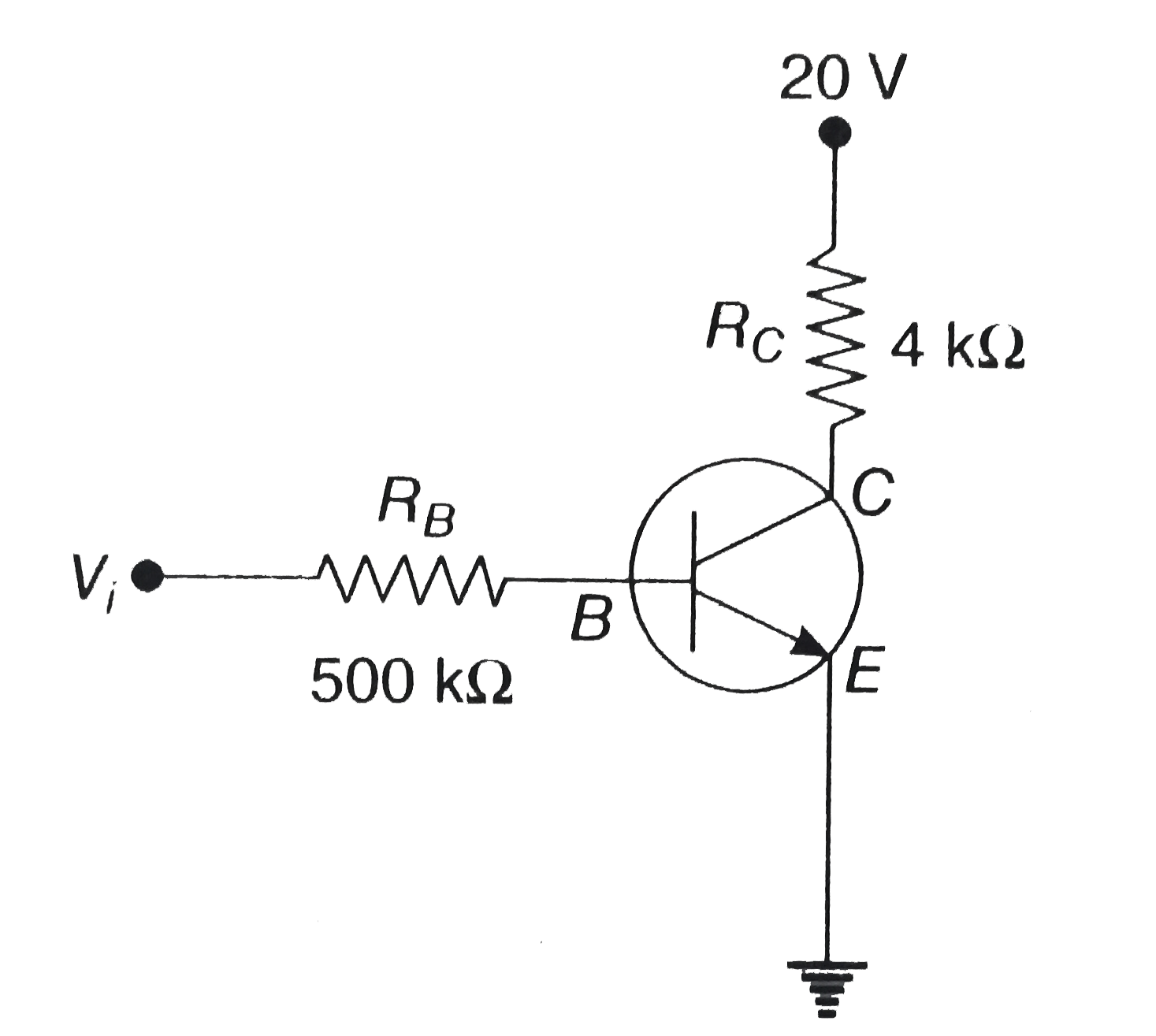
View SolutionIn the circuit shown in the figure, the input voltage Vi is 20V,VBE=0 and VCE=0. The values of IB,IC and β are given by:

View SolutionAn n-p-n transistor in a common-emitter mode is used as a simple voltage-amplifier with a collector current of 4 mA. The terminals of a 8 V battery is connected to the collector through a load-resistance R_L and to the base through a resistance R_B . The collector-emitter voltage V_(CE)=4V , the base-emitter voltage V_(BE) = 0.6 V and the current amplification factor beta_(dc) = 100 . Then
View SolutionThe output characteristics of an n-p-n transistor represent ,[IC= Collector current ,VCE = potential difference between collector and emitter IB = Base current ,VBB - voltage given to base and emitter ]
View Solution

