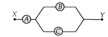
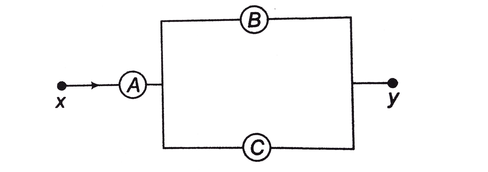
The voltmeters A,B, and C having resistance R, 1.5R and 3R respectively are used in a circuit as shown, When a P.D. is applied between X and Y, the reading of the voltmeters are V1,V2 and V3 respectively Then
 Solution in Kannada
V1=V2=V3
V1<V2=V3
V1>V2>V3
V1>V2=V3
The correct Answer is:A
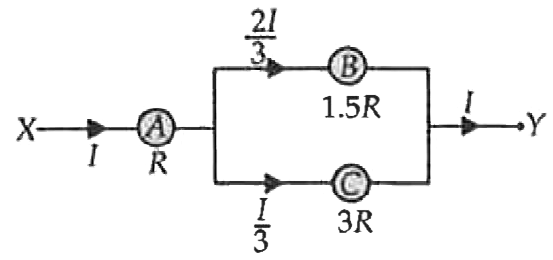
V1=IR
V2=2I3×1.5R=IR,V3=I3×3R=IR
∴V1=V2=V3
Topper's Solved these Questions
Similar Questions
In ruby laser, the stimulated emission is due to transition from
View SolutionWhich of the following graphs correctly represents the variation of heat energy (U) produced in a metallic conductor in a given time as a function of potential difference (V) across the conductor ?
View SolutionConsider the circuit shown in the figure, the cell is ideal. The readings of the ideal voltmeters V_(1) and V_(2) in volts are respectively.
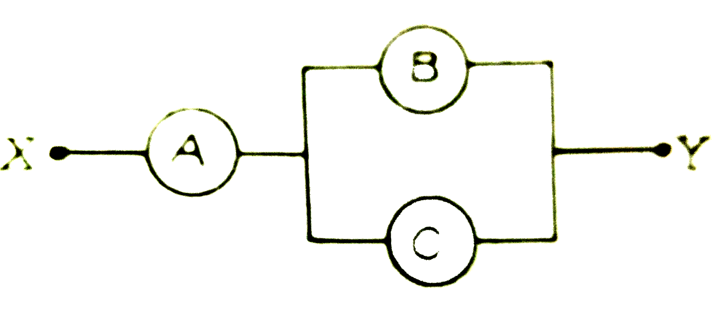
View Solutionआरेख में दिखाये गये वोल्टमीटरों A , B तथा C के प्रतिरोध क्रमशः R, 1.5 R तथा 3 R हैं । जब X तथा Y के बीच कुछ विभवान्तर लगाया जाता है तो इनके पाठ क्रमशः VA,VB तथा VC हैं तब :
View Solutionयदि किसी L-C-R परिपथ में VL,VR,VC तथा V0 क्रमशः प्रेरकत्व, प्रतिरोध, संधारित्र तथा स्रोत में लगे AC वोल्टमीटर के पाठ्यांक हों, तो :
View SolutionThree voltmeters A, B and C having resistances R, 1.5 R and 3 R respectively are used in a circuit as shown. When a potential difference is applied between X and Y, the readings of the voltmeters are V1,V2andV3respectively. Then :
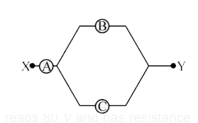
View SolutionA, B and C arc voltmeters of resistance R, 1.5R and 3R respectively as shown in the figure. When some potential difference is applied between X and Y, the voltmeter readings are VA,VBandVC repsectively. Then :
View SolutionA,B and C are voltmeters of resistance R, 1.5 R and 3R respectively as shown in the fig. When some potential difference is applied between X and Y, the voltmeter reading are VA,VBandVC respectively.

View SolutionA, B and C are voltmeters of resistance R, 1.5R and 3R respectively as shown in the figure. When some potential difference is aaplied between X and Y, the voltmeter readings are VA,VB and VC respectively, then

View SolutionA, B and C are voltmeters of resistance R, 1.5R and 3R respectively as in fig. when some P.D. is applied between x and y, the voltmeter readings are V_A, V_B and V_C respectively, then:
View SolutionA, B and C are voltmeters of resistances R, 1.5R and 3R respectively. When some potential difference is applied between x and y the voltmeter readings are V_A, V _B and V_C, then
View SolutionThree voltmeters A,B and C having resistances R, 1.5 R and 3R respectively are used in a circuit as shown
 . When a P.D. is applied between X and Y, the reading of the voltmeters are V1,V2 and V3 respectively. Then....
View SolutionA,B and C are voltmeters of resistances R,1.5R and 3R respectively. When some potential difference is applied between x and y the voltmeter readings are VA,VBandVC, then
View SolutionConsider the circuit shown in the figure, the cell is ideal. The readings of the ideal voltmeters V_(1) and V_(2) in volts are respectively.
View SolutionThree voltmeters A, B and C having resistances R, 1.5 R and 3 R respectively are used in a circuit as shown. When a potential difference is applied between X and Y, the readings of the voltmeters are V_1, V_2 and V_3 respectively. Then :
View Solution
