For the potentiometer circuit shown in the given figure, points X and Y represent the two terminals of an unknown emf ε . A student observed that when the jockey is moved from the end A to the end B of the potentiometer wire, the direction of the deflection in the galvanometer remains in the same direction. What may be the two possible faults in the circuit that could result in this observations ? If the galvanometer deflection at the end B is (i) more, (ii) less, than that at the end A which of the two faults," listed above, would be there in the circuit ? Give reasons in support of your answer in each case.
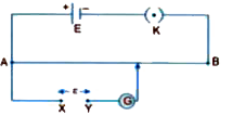
Two possible faults in the circuit can be :
1. Positive terminal of unknown emf source e is not connected to point A, where positive terminal of battery E has been connected.
2. Emf of battery E is less than the unknown emf ε .
(i) If on sliding the jockey from the end A to end B galvanometer deflection gradually increases then it means that connections of unknown emf ε are wrong because then in accordance with Kirchhoff.s laws potential is gradually increasing from A to B.
(ii) If on sliding the jockey from the end A to end B galvanometer deflection decreases but null point is not obtained then it means that the emf of battery E is less than unknown emf ε and hence deflection is in one direction only.
Similar Questions
Knowledge Check
In the following diagram the deflection in the galvanometer in a potentiometer circuit is zero. Then:-
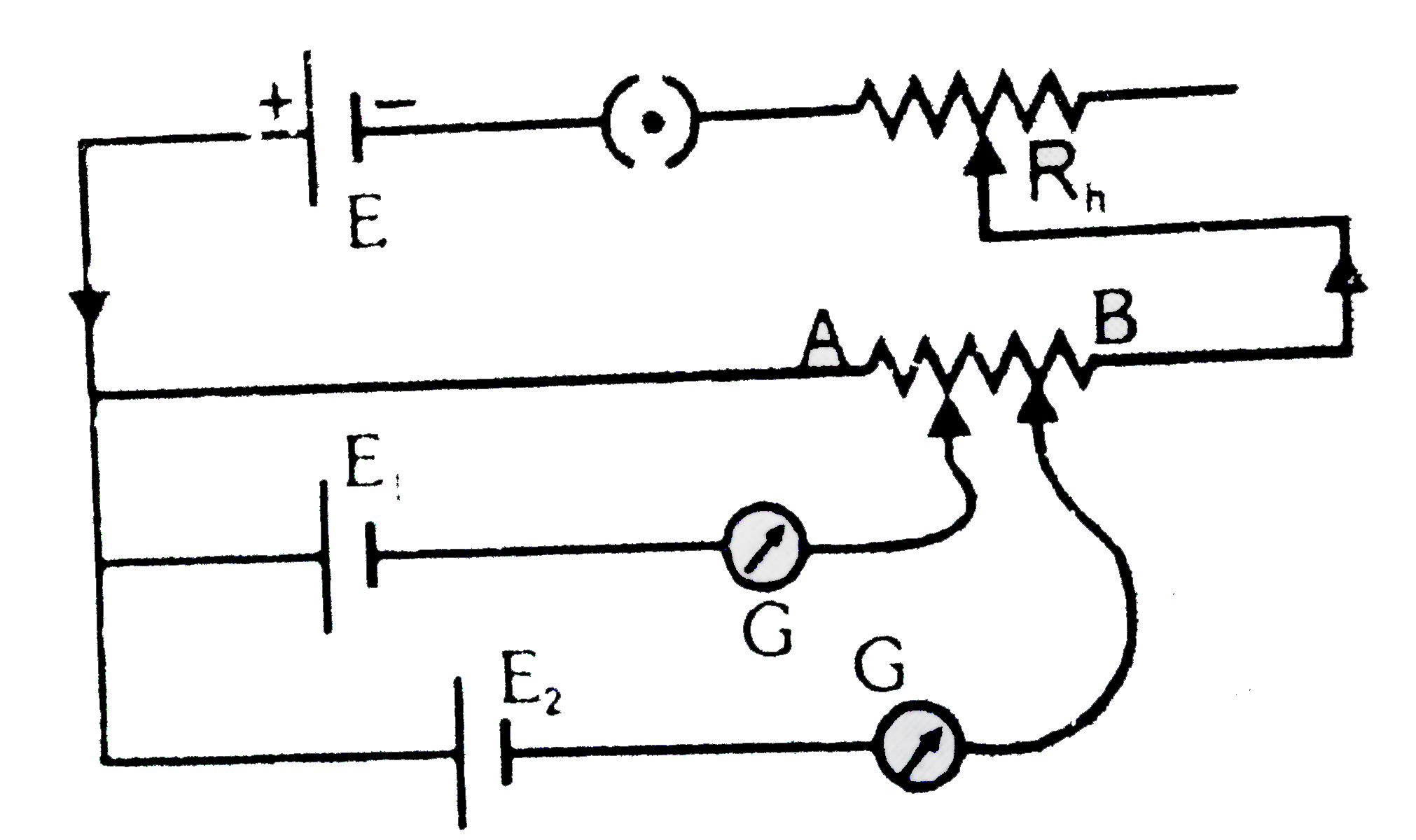 AE1>E2BE2>E1CE1=E2DE1+E2=E
In a potentiometer circuit, all the +ve terminals should be connected at
Aone pointBdifferent pointsCalternate pointsDeither 'b' or 'c'A potentiometer circuit shown in the figure is set up to measure e.m.f. of a cell E . As the point P moves from X to Y the galvanometer G shows deflection always in one direction, but the deflection decreases continuously until Y is reached. In order to obtain balance point between X and Y it is necessary to
 ADecreases the resistance RBIncrease the resistance RCReverse the terminals of battery VDReverse the terminals of cell E
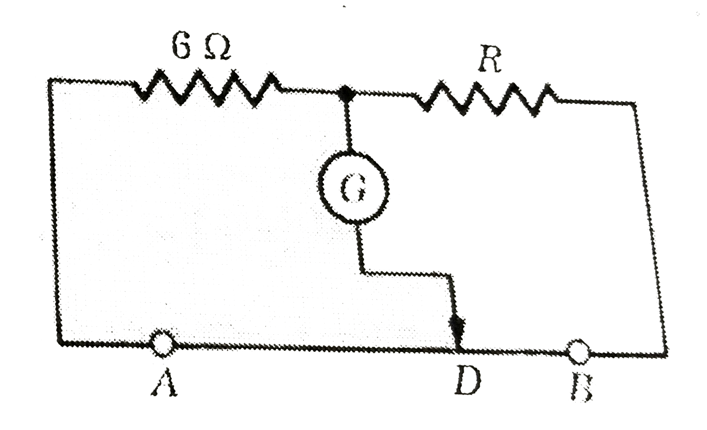
The potentiometer wire AB shown in figure. Is 50 cm long. When AD=30cm, no deflection occurs in the galvanometer. Find R
View SolutionIn order to determine the internal resistance of a primary cell by means of potentiometer the emf of the battery connected across the ends of the potentiometer wire should be
View SolutionThe potentiometer wire AB is 600cm long. At what distance (in cm) from A should the jockey J touch the wire to get zero deflection in the galvanometer?
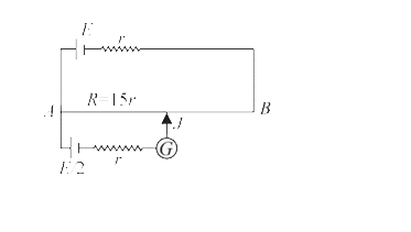
View SolutionThe potentiometer wire AB is 600cm long. At what distance (in cm) from A should the jockey J touch the wire to get zero deflection in the galvanometer?

View SolutionThe potentiometer wire AB is 600 cm long . At what distance (in cm) from A should the jockey J touch the wire to get zero deflection in the galvanometer?
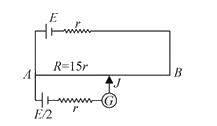
View Solution


