Describe the simple filter circuit for obtaining smooth rectified voltage from junction diode rectifier. Solution in Gujrati
Video Solution
Text Solution
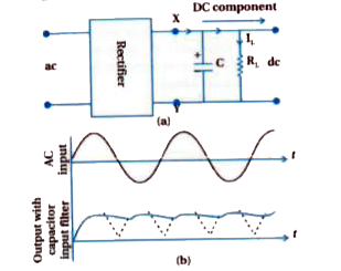
The rectified voltage is in the form of pulses of the shape of half sinusoids. Thought it is unidirectional it does not have steady value.
To get steady dc output from the pulsating voltage normally a capacitor is connected across the output terminals parallel to the load RL or one can also use an inductor in series will RL for the same purpose. Since these additional circuit appear to filter out the ac ripple and give a pure dc voltage, so they are called filters.
When the voltage across the capacitor is rising it gets charged.
If there is no external load, it remains charged to the peak voltage of the rectified output.
When there is a load, it gets discharged through the load and the voltage across it begins to fall.
In the next half cycle of rectified output it again gets charged to the peak value. This is shown in figure.

The rate of fall of the voltage across the capacitor depends inversely upon the product of capacitance C and the effective resistance RL used in the circuit and is called the time constant [t=RC].
To make the time constant large value of C should be large.
So capacitor input filters use large capacitors.
The output voltage obtained by using capacitor input filter is nearer to the peak voltage of the rectified voltage.
This type of filter is most widely used in power supplies.
|
Similar Questions
Draw a circuit diagram of a full wave rectifier made up of junction diode.
View SolutionDraw the circuit diagram of a half wave rectifier made up of junction diode .
View SolutionDraw the circuit diagram of a half-wave rectifier made up of junction diode.
View SolutionDraw a circuit diagram of a full wave rectifier using junction diode.
View SolutionDraw the circuit diagram of a full wave rectifier made up of junction diode.
View SolutionDescribe with neat circuit diagram, the working of junction diode as a full wave rectifier. Show that for an ideal full wave rectifier, the efficiency is 81.2%.
View SolutionWhat is a p-n junction diode ? With a neat circuit diagram, describe the operation of a full-wave rectifier using junction diodes.
View SolutionDraw a labelled circuit diagram of half wave rectifier using junction diode
View Solution
