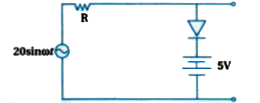
Assuming the ideal diode, draw the output waveform for the circuit given in figure. Explain the waveform. Solution in Gujrati
Here, V=20sin(ωt) and so maximum voltage is Vm=20V. It means that input voltage would change from +20V to -20V.

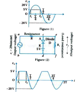
(i) For time intervals from 0 to t1 and from t2 to T2 when vi<5V, potential at anode is less than potential at cathode (VA<VK) and so diode is reverse biased and so no current would pass through it. Hence input signal voltage would appear directly across load resistance RL in the output. Hence waveform of output voltage v0 across RL would be similar to input voltage vi, which is shown in figure 3.
(ii) At instants t=t1andt=t2, when vi=5V, no current passes through resistance R and diode D and so v0=vi=5V which is shown in figure 3.
(iii) Now, for time interval from t1 to t2,vi>5V and so diode is forward biased where its resistance becomes zero and so potential difference across it will also be zero. Hence, in the time interval from t1 to t2,v0=5
V = constant (which is the battery voltage).
(iv) Now, for negative half cycle from T2 to T, diode D is reverse biased and so no current passes through it due to infinite resistance and so input signal would pass directly through RL and so waveform of v0 across RL would be similar to waveform of vi which is shown in figure 3.
Similar Questions
Assuming the ideal diode, draw the output waveform for the circuit given in fig. (a), explain the waveform
View SolutionAssuming that the diode is an ideal diode, make the output waveform of the circuit in Fig. Explain this wave form.
View SolutionExplain the working of p-n junction diode as a full wave rectifier with circuit diagram. Give input and output waveforms.
View SolutionA waveform shown when applied to the following circuit will produce which of the following output waveform? [Assuming ideal diode configuration and R1=R2]

View Solutionदिये गये परिपथ में डायोड के आर-पार निर्गत तरंग-रूप आरेखित कीजिए।

View SolutionAssuming the ideal diode, draw the output waveform for the circuit given in Fig. EP14.35. Explain the waveform.
View SolutionWhat is an ideal diode ? Draw the output waveform across the load resistor R, If the wavelength is as shown in the figure.
View Solution
