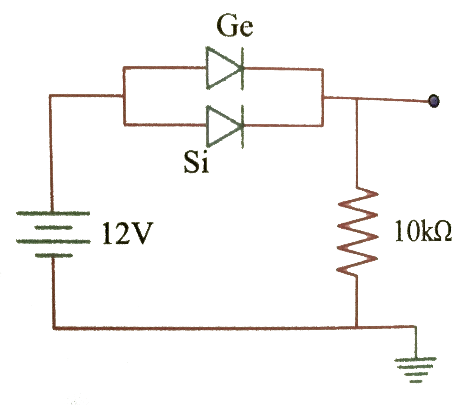
Two junction diodes, one of germanium (Ge) and other of silicon (Si) are connected as shown in fig to a battery of 12V and a load resistance 10kΩ. The germanium diode conducts at 0.3V and silicon diode at 0.7V. When current flows in the circuit, the potential of terminal Y will be
(##AKS_NEO_CAO_PHY_XII_V02_C_C06_SLV_013_Q01.png" width="80%">
The Ge diode conducts for a p.d of 0.3V, therefore the current passes through it and the Si diode do not conduct. Hence the potential of terminal Y = 12-0.3 = 11.7V
Topper's Solved these Questions
- SEMICONDUCTOR DEVICESBook:AAKASH SERIESChapter:SEMICONDUCTOR DEVICESExercise:EXERCISE -I (ENERGY BANDS AND CLASSIFICATION OF SOLIDS )
Explore 43 Videos
- SEMICONDUCTOR DEVICESBook:AAKASH SERIESChapter:SEMICONDUCTOR DEVICESExercise:EXERCISE -I (P-N JUNCTION DIODE)
Explore 35 Videos
- SEMICONDUCTOR DEVICESBook:AAKASH SERIESChapter:SEMICONDUCTOR DEVICESExercise:Problems (LEVEL-II)
Explore 7 Videos
- RAY OPTICSBook:AAKASH SERIESChapter:RAY OPTICSExercise:PROBLEMS ( LEVEL-II)
Explore 50 Videos
- UNITS AND MEASUREMENTBook:AAKASH SERIESChapter:UNITS AND MEASUREMENTExercise:PRACTICE EXERCISE
Explore 45 Videos
Similar Questions
Two junction diodes, one of germanium (Ge) and other of silicon (Si) are connected as shown in fig to a battery of 12V and a load resistance 10kΩ. The germanium diode conducts at 0.3V and silicon diode at 0.7V. When current flows in the circuit, the potential of terminal Y will be
 .
.
View SolutionTwo junction diodes, one of germanium (Ge) and other of silicon (Si) are connected as shown in fig to a battery of 12V and a load resistance 10kΩ. The germanium diode conducts at 0.3V and silicon diode at 0.7V. When current flows in the circuit, the potential of terminal Y will be
 .
.
View Solution
Knowledge Check
In a common emitter transistor circuit, the base current is 40μA , then VBE is
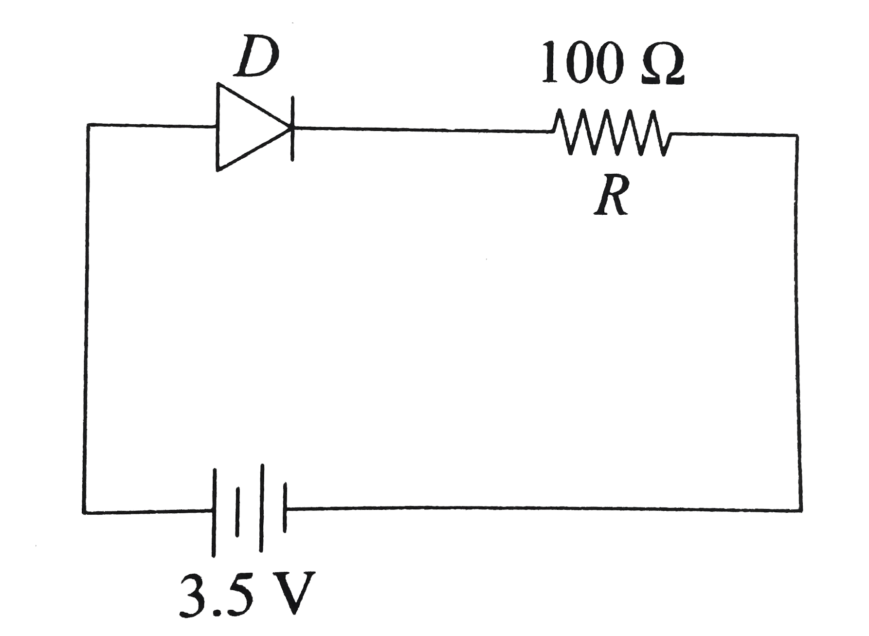
(##AAK_P7_NEET_PHY_SP7_C29_E03_025_Q01.png" width="80%">A2VB0.2VC0.8VDZeroIn the given figure, a diode D is connected to an external resistance R=100Ω and an emf of 3.5V. If the barrier potential developed across the diode is 0.5V, the current in the circuit will be :
 A35mAB30mAC40mAD20mA
In the given figure, a diode D is connected to an external resistance R=100Ω and an emf of 3.5V. If the barrier potential developed across the diode is 0.5V, the current in the circuit will be :
 A20 mAB35 mAC30 mAD40 mA
A p-n junction diode in forward bias is connected to a battery of 4 V and a resistance of 80 ω as shown in the ajoining determine the maximum current in the circuit barrier potential of p-n diode is 0.2 V

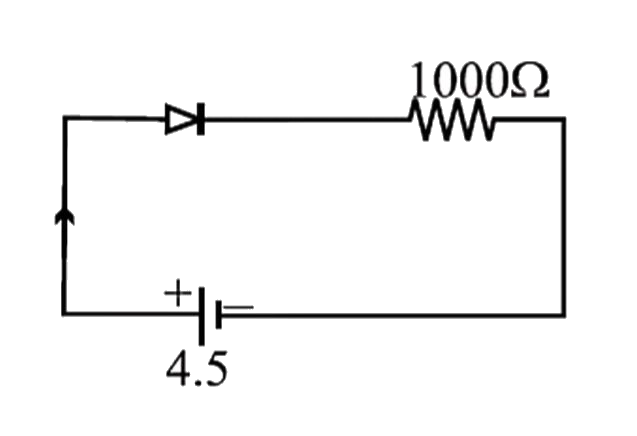
View SolutionA P-N junction diode connected to a battery of e.m.f. 4.5 V and an external resistance of 1000Ω. What is the value of current in the circuit, if potential barrier in the diode =0.5V

View SolutionA P-N junction diode connected to a battery of e.m.f. 4.5 V and an external resistance of 1000Ω. What is the value of current in the circuit, if potential barrier in the diode =0.5V

View SolutionIn the given figure, a diode D is connected to an external resistance R=100Ω and an emf of 3.5V. If the barrier potential developed across the diode is 0.5V, the current in the circuit will be :

View SolutionFind the effective resistance between points A and B for the network shown in the figure below.
(ARH_NEET_PHY_OBJ_V02_C03_S01_027_Q01.png" width="80%">
View Solution

