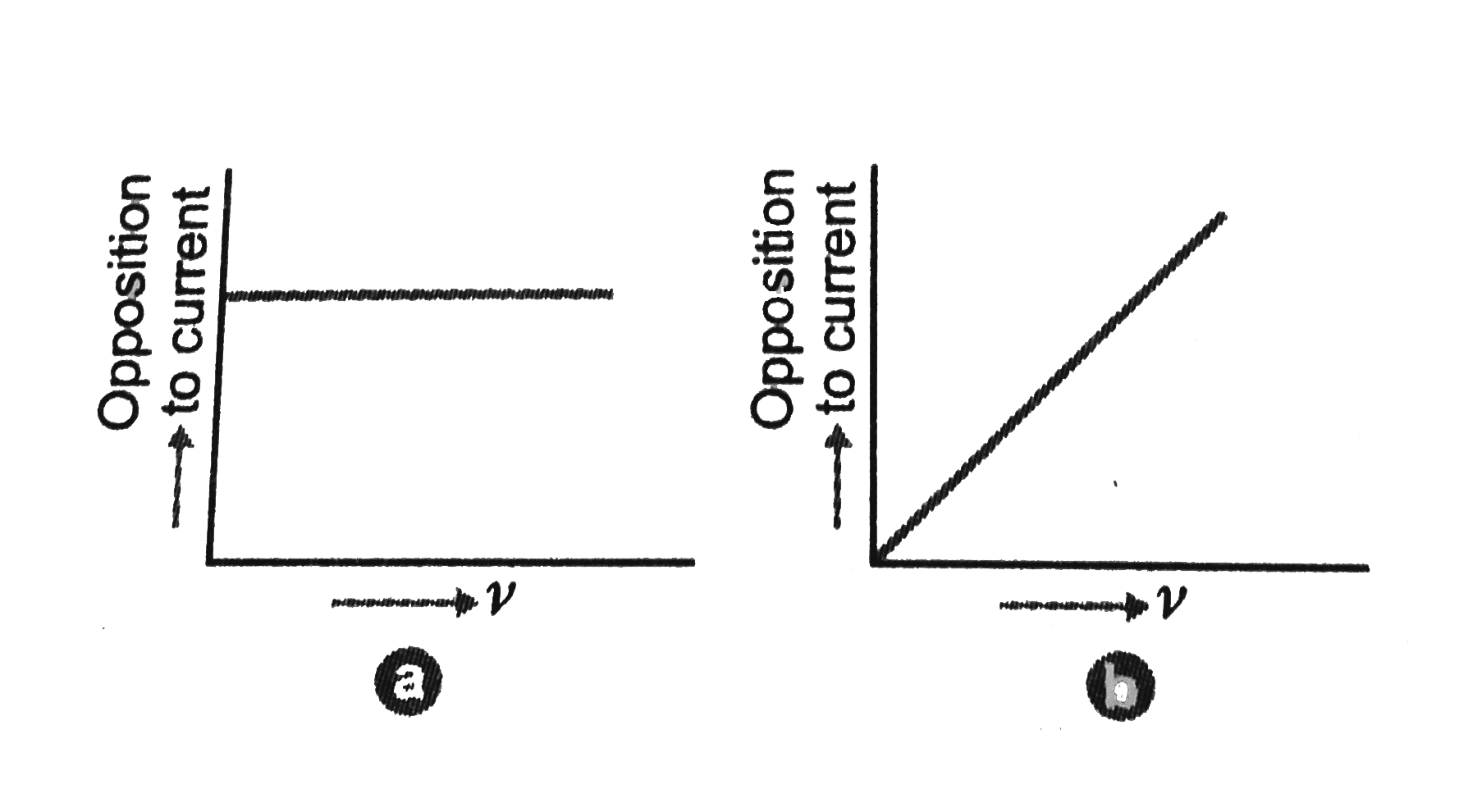
(a) The graphs (i) and (ii) represent the variation of the opposition offered by the circuit elements to the flow of alternating current with frequency of the applied emf. Identify the circuit element corresponding to each graph.
(b) Write the expression for the impedance offered by the series combination of above two elements connected across the a.c. source. Which will be ahead in phase in this circuit, voltage or current ?
(a) The circuit element shown in Fig. 7.17(i) is a resistor, because opposition offered by it for flow of current is a constant and does not change with frequency. The circuit element shown in Fig. 7.17 (ii) is an inductor because its opposition to current is increasing regularly with increase in frequency and it is possible for only an inductor as XL=Lω=L2πv.

(b) The impedance offered by the series combination of R and L is given by :
Z=√R2+X2L=√R2+(Lω)2
In a L-R circuit voltage is ahead in phase than current by a phase angle ϕ, where tanϕ=XLR.
Similar Questions
The graphs shown in Fig. represent the variation of opposition offered by the circuit element of the flow of a.c. with frequency of applied e.m.f. Iddntify the circuit element .
View SolutionWhich of the following graphs represent the variation of current(I) with frequency (f) in an AC circuit containing a pure capacitor?
View Solution
Knowledge Check
An LCR circuit is connected to a source of alternating current. At resonance, the applied voltage and the current flowing through the circuit will have a phase difference of
Aπ/4BzeroCπDπ/2An alternating current of frequency 'f' is flowing in a circuit containing a resistance R and a choke L in series. The impedence of this circuit is
AR+2πfLB√R2+4π2f2L2C√R2+L2D√R2+2πfLWhich of the following graphs represent the variation of current(I) with frequency (f) in an AC circuit containing a pure capacitor?
A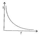 B
B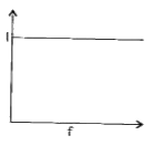 C
C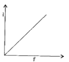 D
D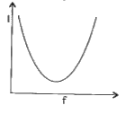
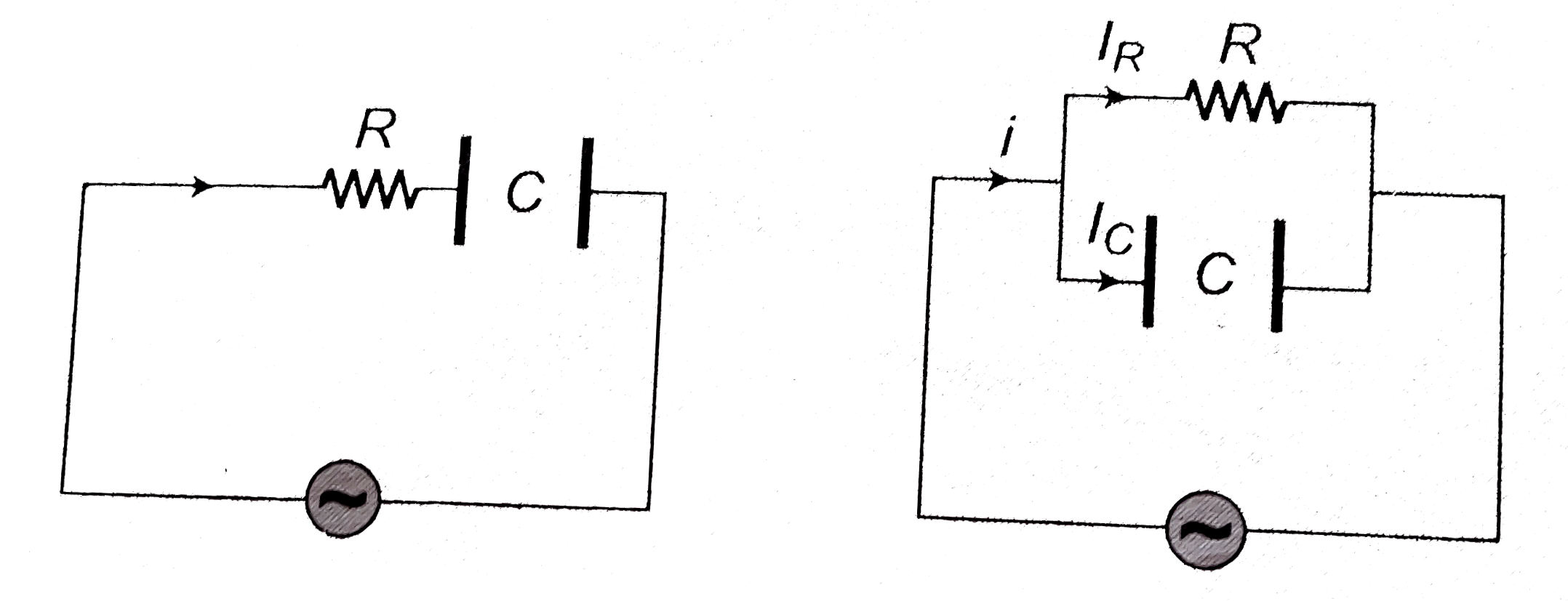
For a resistance R and capacitance C in series the impedance is twice that of a parallel combination of the same elements What is the frequency of applied emf .
 .
.
View SolutionA reactive element, in an a.c. circuit, causes the current flowing (i) to lag in phase by π2,
(ii) to lead in phase by π2 with respect to the applied voltage. Identify the element in each case.
View SolutionSketch a graph showing the variation of impedance of LCR circuit the frequency of applied voltage.
View SolutionAn alternating current by frequency v is flowing in a circuit containing a resistance R and inductance L in series. The impedance of this circuit is
View SolutionIn an a.c. series circuit, the instantaneous current is maximum when the instantaneous voltage is maximum. The circuit element connected to the source will be
View Solution

