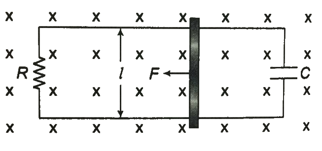
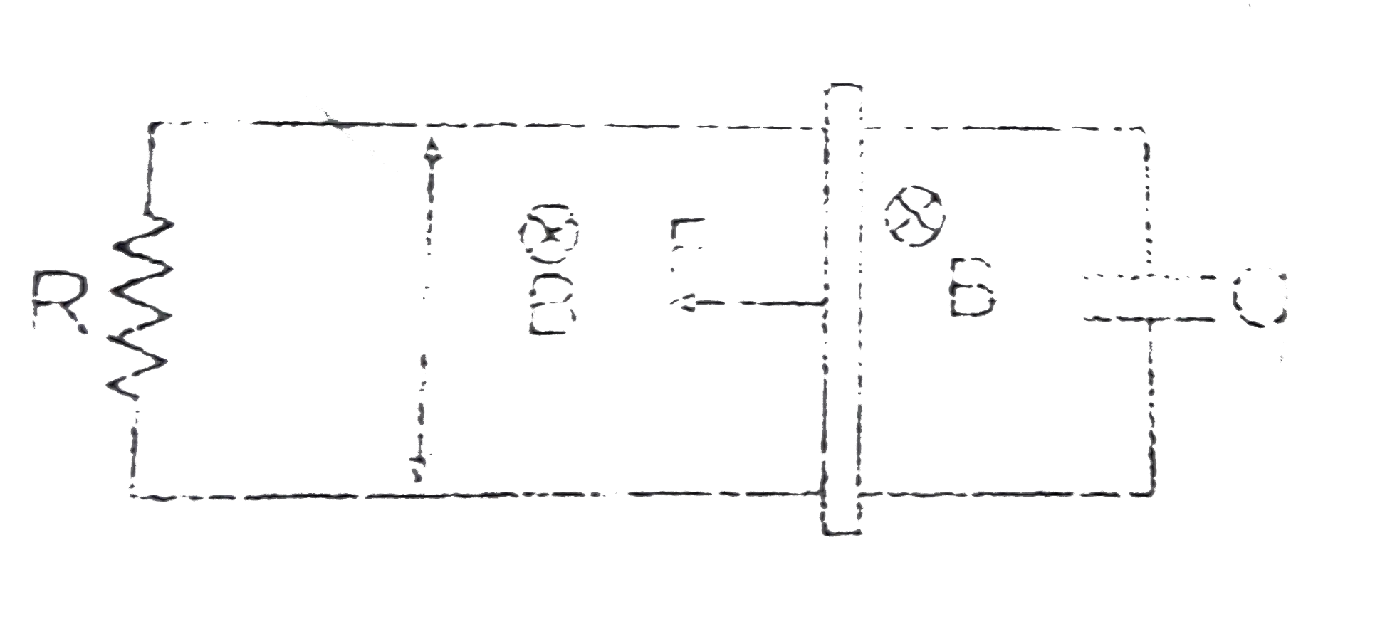
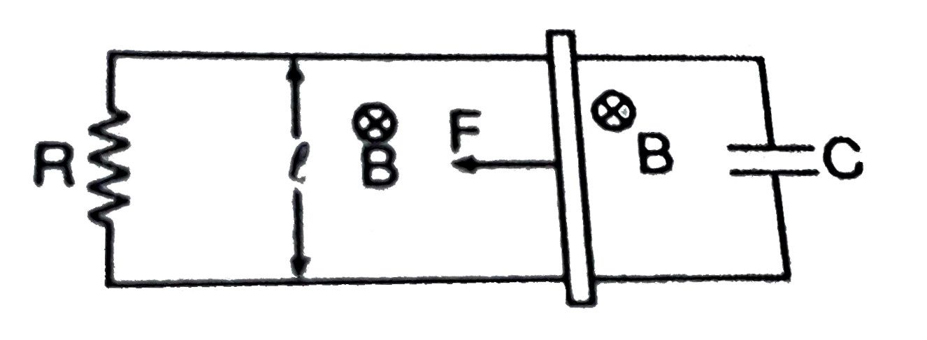
Two parallel long smooth conducting rails separated by a distance l are connected by a movable conducting connector of mass m. Terminals of the rails are connected by the resistor R and the capacitor C as shown in figure. A uniform magnetic field B perpendicular to the plane of the rail is switched on. The connector is dragged by a constant force F. Find the speed of the connector as a function of time if the force F is applied at t=0. Also find the terminal velocity of the connector.
The correct Answer is:B
Step by step video solution for Two parallel long smooth conducting rails separated by a distance l are connected by a movable conducting connector of mass m. Terminals of the rails are connected by the resistor R and the capacitor C as shown in figure. A uniform magnetic field B perpendicular to the plane of the rail is switched on. The connector is dragged by a constant force F. Find the speed of the connector as a function of time if the force F is applied at t = 0. Also find the terminal velocity of the connector. by Physics experts to help you in doubts & scoring excellent marks in Class 12 exams.
Updated on:21/07/2023Topper's Solved these Questions
- ELECTROMAGNETIC INDUCTIONBook:RESONANCE ENGLISHChapter:ELECTROMAGNETIC INDUCTIONExercise:Exercis-2 PART 3
Explore 10 Videos
- ELECTROMAGNETIC INDUCTIONBook:RESONANCE ENGLISHChapter:ELECTROMAGNETIC INDUCTIONExercise:Exercis-2 PART 4
Explore 6 Videos
- ELECTROMAGNETIC INDUCTIONBook:RESONANCE ENGLISHChapter:ELECTROMAGNETIC INDUCTIONExercise:Exercis-2 PART 1
Explore 14 Videos
- ELECTRODYNAMICSBook:RESONANCE ENGLISHChapter:ELECTRODYNAMICSExercise:Advanced level problems
Explore 29 Videos
- ELECTROSTATICSBook:RESONANCE ENGLISHChapter:ELECTROSTATICSExercise:HLP
Explore 38 Videos
Similar Questions
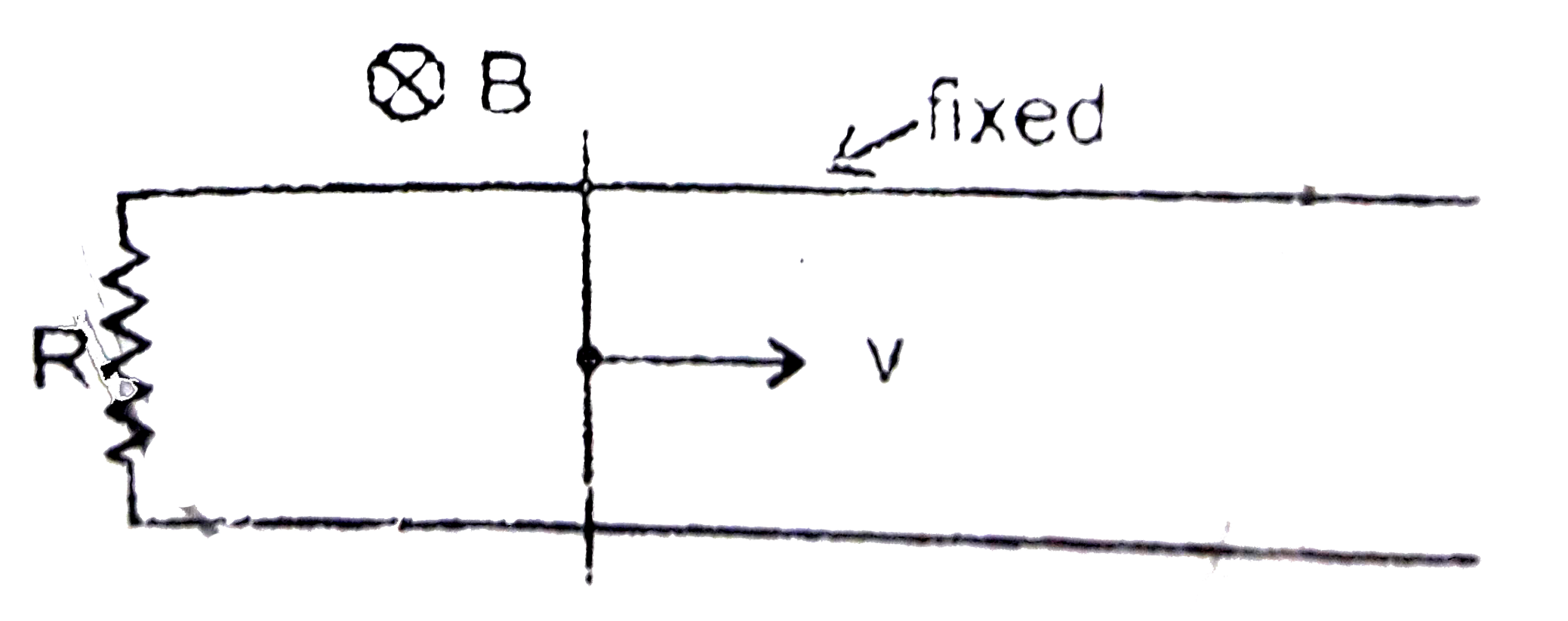
A resistance R is connected between the two ends of the parallel smooth conducting rails.A conducting rod lies on these fixed horizontal rails and a uniform constant magnetic field B exists perpendicular to the plane of the rails as shown in the figure.If the rod is given a velocity v and released as shown in figure, it will stop after some time, which option are correct:
View SolutionFigure shows a conducting rod of negligible resistance that can slide on smooth U-shaped rail made of wire of resistance 1Ω/m. Position of the conducting rod at t=0 is shown. A time dependent magnetic field B=2t tesla is switched on at t=0
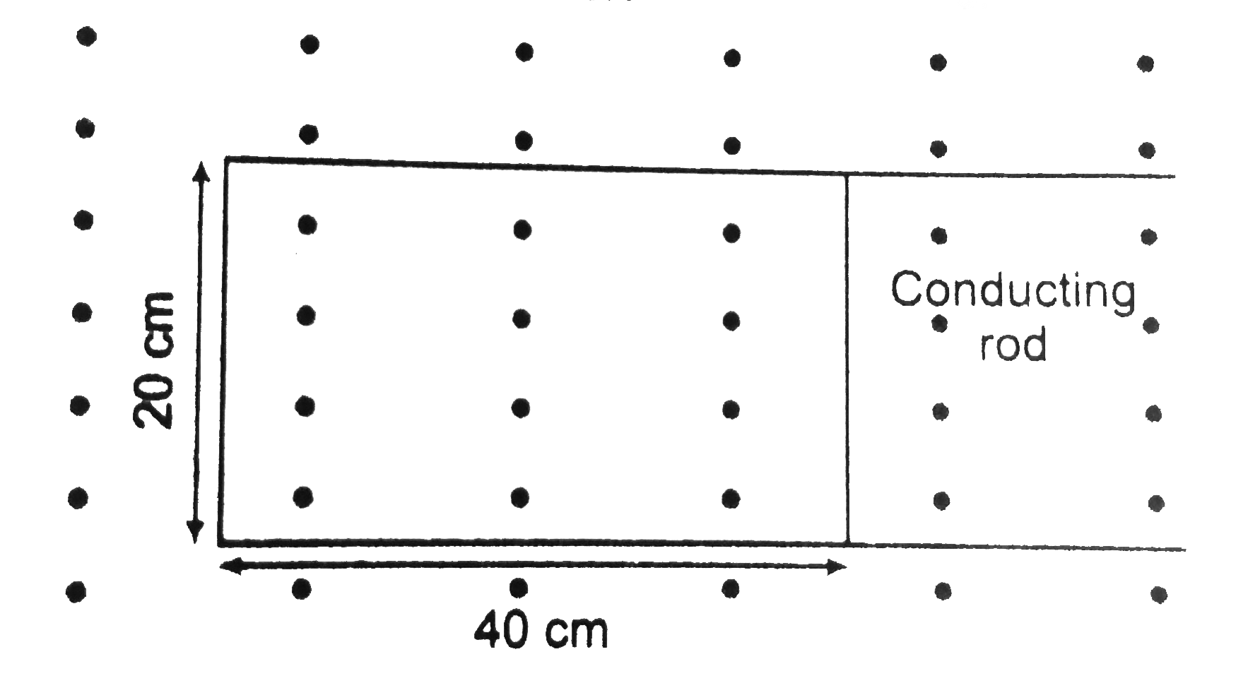
The current in the loop at t=0 due to induced emf is
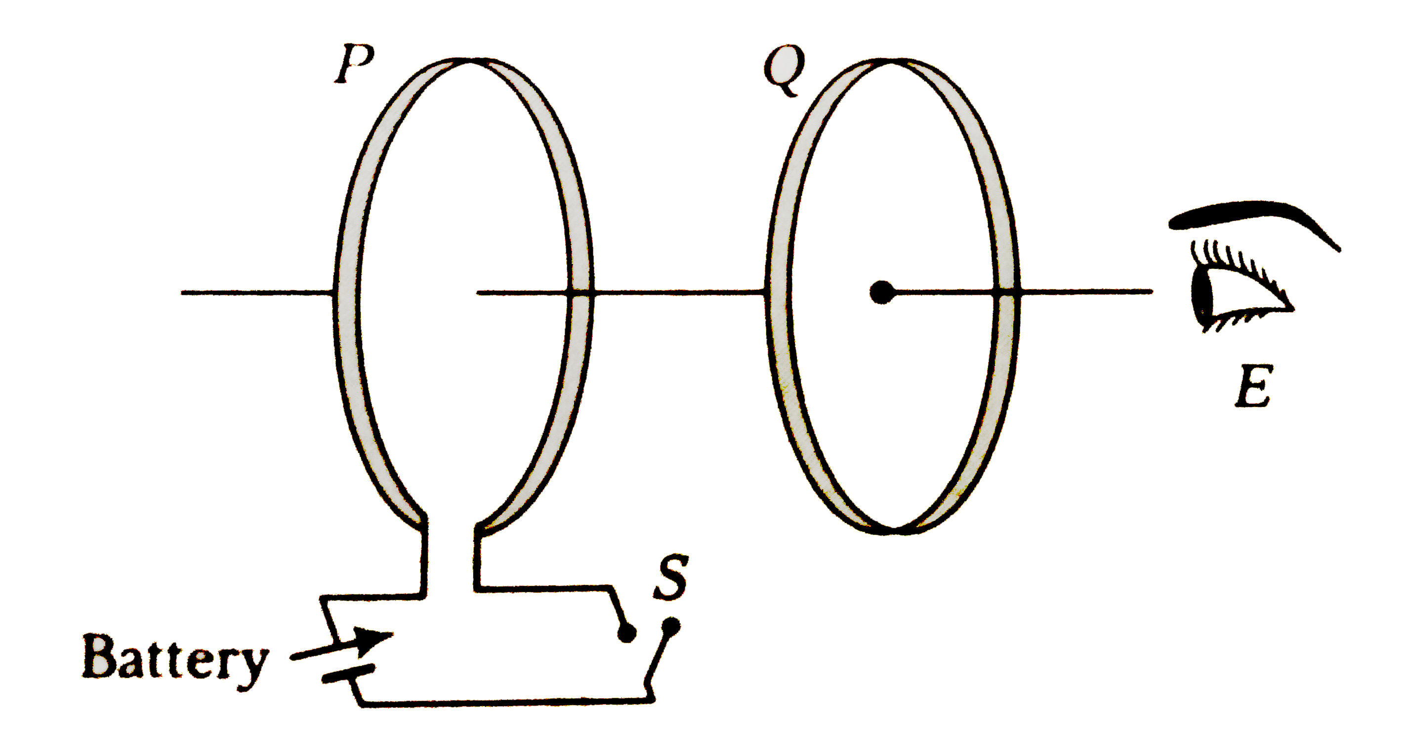
View SolutionAs shown in figure, P and Q are two co-axial conducting loops separated by some distance. When the switch S is closed, a clockwise current IP flows in P (as seen by E) and an induced current IQ1 flows in Q. The switch remains closed for a long time. When S is opened, a current IQ2 flows in Q.
Then, the directions of IQ1 and IQ2 (as seen by E) are
View SolutionCalculate the magnetic moment (in Am2 ) of a thin wire with a current I = 8A, wound tightly on half a torus (see figure). The diameter of the cross section of the torus is equal to d = 5 cm, and the number of turns is N = 500.

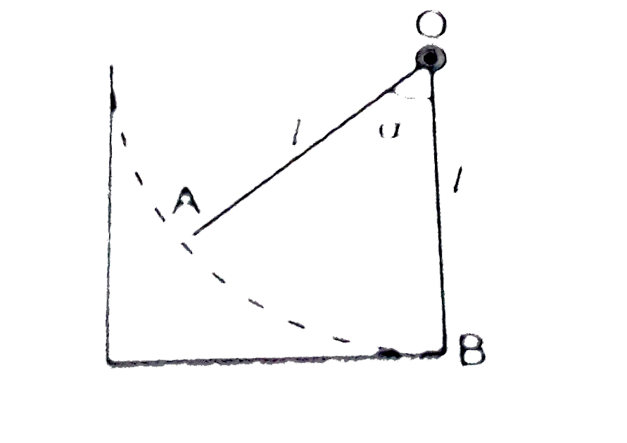
View SolutionAn electrometer consister of a fixed vertical metal bar OB at the top of which is attached a thin rod OA which gets deflected from the bar under the action of an electric charge (fig.). The rod can rotate in vertical plane about fixed horizontal axis passing through O. The reading is taken on a quadrant graduated in degrees. The length of the rod is l and its mass is m. what will be the charge when the rod of such an electrometer is deflected through an angle α in equilibrium. Find the answer using the following two assumptions :
The charge on the electrometer is equally distributed between the bar & the rod and the charges are concentrated at point A on the rod & at point B on the bar.
View SolutionTwo parallel long smooth conducting rails separated by a distance l are connected by a movable conducting connector of mass m . Terminals of the rails are connected by the resistor R and the capacitor C as shown in figure. A uniform magnetic field B perpendicular to the plane of the rail is switched on. The connector is dragged by a constant force F . Find the speed of the connector as a function of time if the force F is applied at t = 0 . Also find the terminal velocity of the connector.
View SolutionA conducting rod of length is moved at constant velocity v0 on two parallel, conducting, smooth, fixed rails, that are placed in a uniform constant magnetic field B perpendicular to the plane for the rails as shown in Fig. A resistance R is connected between the two ends of the rails.
Then which of the following is/are correct:

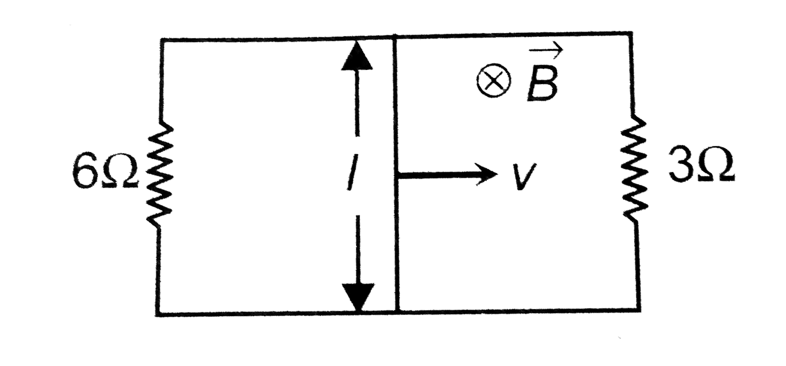
View SolutionA rectangle loop with a sliding connector of length l=1.0m is situated in a uniform magnetic field B=2T perpendicular to the plane of loop. Resistance of connector is r=2Ω. Two resistance of 6Ω and 3Ω are connected as shown in figure. the external force required to keep the connector moving with a constant velocity v=2m/s is
View SolutionA pair of parallel conducting rails lie at right angle to a uniform magnetic field of 2.0T as shown in the fig. two resistor 10Omega and 5Omega are to slide without friction along the rail. The distance between the conducting rails is 0.1m . Then
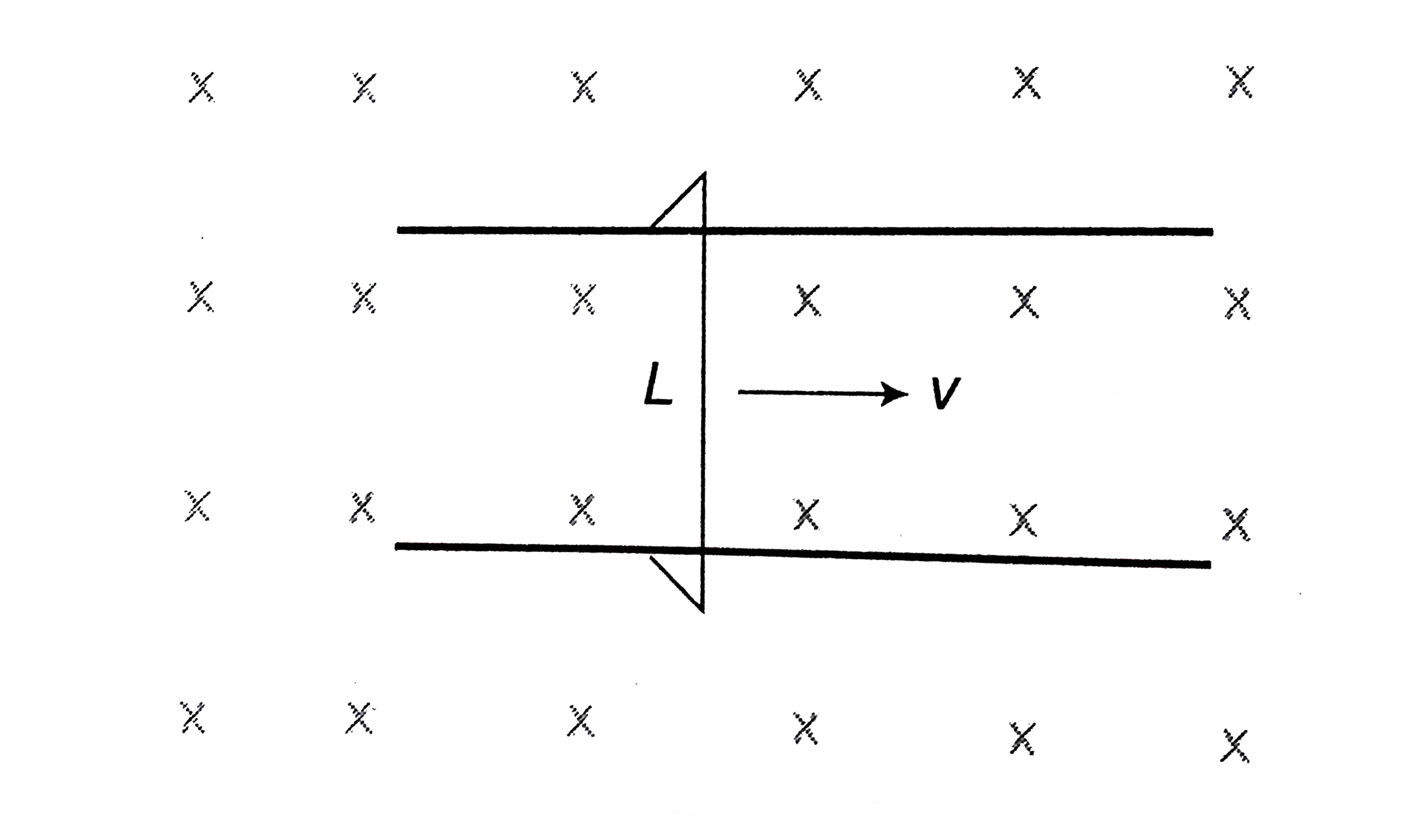
View SolutionFigure shows a wire sliding on two parallel, conducting rails placed at a separation L . A magnetic field B exists in a direction perpendicular to the plane of the rails. What force is necessary to keep the wire moving at a constant velocity V ?
View SolutionTwo smooth horizontal parallel conducting rails are connected with a capacitor and a resistor at the two ends as shown. A uniform conducting rod PQ of mass 'm' and length 'l' is dragged with a constant horizontal force 'F'. The terminal velocity aquired by the conducting rod is
View SolutionTwo long rails are hporizontal and parallel to each. On one end, the rails are connected by a resistance R and on the other end a cpacitor of capacitance C is connected as shown in the figure . A connecter of mass m and length l can slide on the rails without friction. Uniform magnetic field B, perpendicular to he plane of hte gigure exists in space. A constant horizontal force F starts acting on hte connector. What is the acceleration of connector when its veleocity is 34 of its terminal velocity?
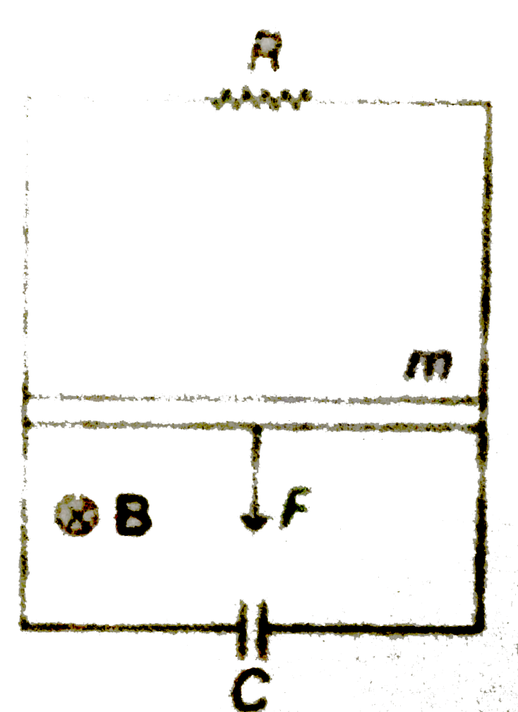
View SolutionTwo parallel long smooth conducting rails separated by a distance l=10cm are connected by a movable conducting connector of mass m=4mg.Terminals of the rails are connected by the resistor R=2Ω & the capacitor C=1μF as shown.A uniform magnetic field B=20T perpendicular to the plane of the rails is swiched on.The connector is dragged by a constant force F=10N.The speed of the connector as function of time if the force F is applied at t=0 is equal to v−5(1−e−x×104×tm/s).Find the value of x.
View SolutionTwo parallel long smooth conducting rails separated by a distance l=10cm are connected by a movable conducting connector of mass m = 4mg. Terminal of the rails are connected by the resistor R=2Ω & the capacitor C=1μF as shown. A uniform magnetic field B=20T perpendicular to the plane of the rails is switched on. The connector is dragged by a constant force F=10 N. The speed of the connector as function of time if the force F is applied at t=0 is equal to v=5(1−e−x×104×t)m/s. Find the value of x.
View SolutionIn the network shown, the connector of mass m, length l and negligible resistance can smoothly side along two fixed parallel rails. The capacitor is initially uncharged and ET a uniform magnetic field B exists in the region directed into the plane of paper. If the switch S is closed at t=0 then the charge on the capacitor after long time is
View SolutionTwo parallel long smooth conducting rails separated by a distance l are connected by a movable conducting connector of mass m. Terminals of the rails are connected by the resistor R and the capacitor C as shown in figure. A uniform magnetic field B perpendicular to the plane of the rail is switched on. The connector is dragged by a constant force F. Find the speed of the connector as a function of time if the force F is applied at t=0. Also find the terminal velocity of the connector.

View Solution
