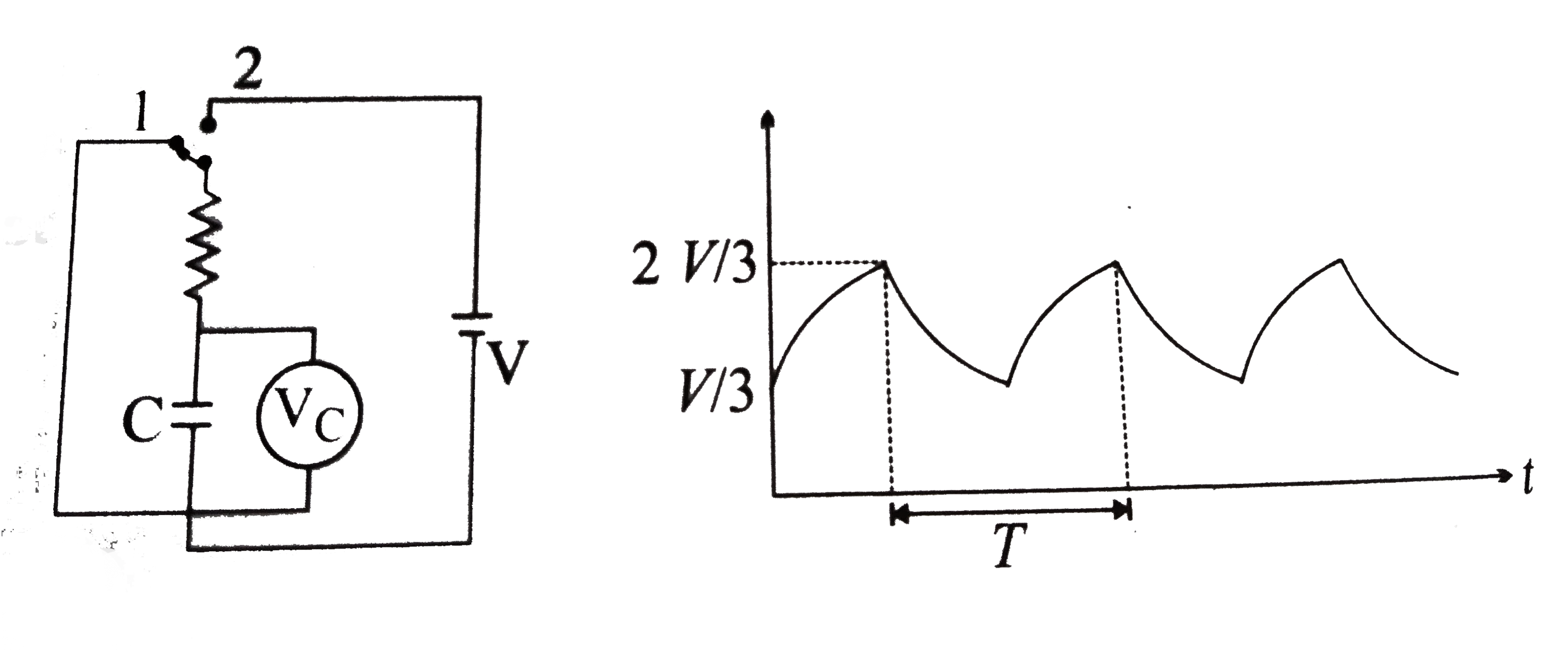
The switch in Figure (a) closes when Vc=2V/3 and opens when Vc=V/3. The voltmeter reads a voltage as plotted in figure (b). What is the period T of the waveform? (take R1=6R and R2=3R, and ln2=0.7 if required)
(a) 
12RC
8.4RC
11RC
none of these
The correct Answer is:B
When the switch closes at Vc=2V/3 the capacitor discharges through R2=3R
T (discharge) =3RCln2 (since the voltage halves).
The charging occurs through R1+R2=9R
T (charge) =9RCln2
T=12RCln2≈8.4RC
Similar Questions
VC is the ideal voltmeter in the figure. Resistance of the resistor shown is R. Initially the switch is in position 2 when charging of the capacitor starts. Initially the capacitor was uncharged. The switch in circuit shifts automatically from 2 to 1 when VC>2V/3 and goes back to 2 from 1 when VC<V/3. The ideal voltmeter reads voltage across capacitor as plotted. What is the period T of the wave from in terms of R and C ?
 ,
,
View SolutionIn the given figure, when temperature is increased then which of the following increases
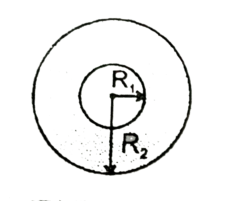
(A) R1 (B) R1 (C )R2−R1
View SolutionAn ammeter A, a voltmeter V and a resistance R are connected as shown in the figure. If the voltmeter reading is 1.6V and the ammeter reading is 0.4A, then R is
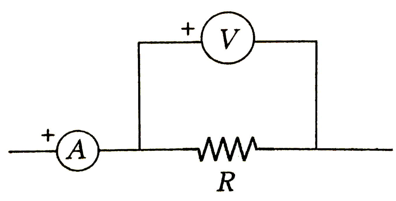
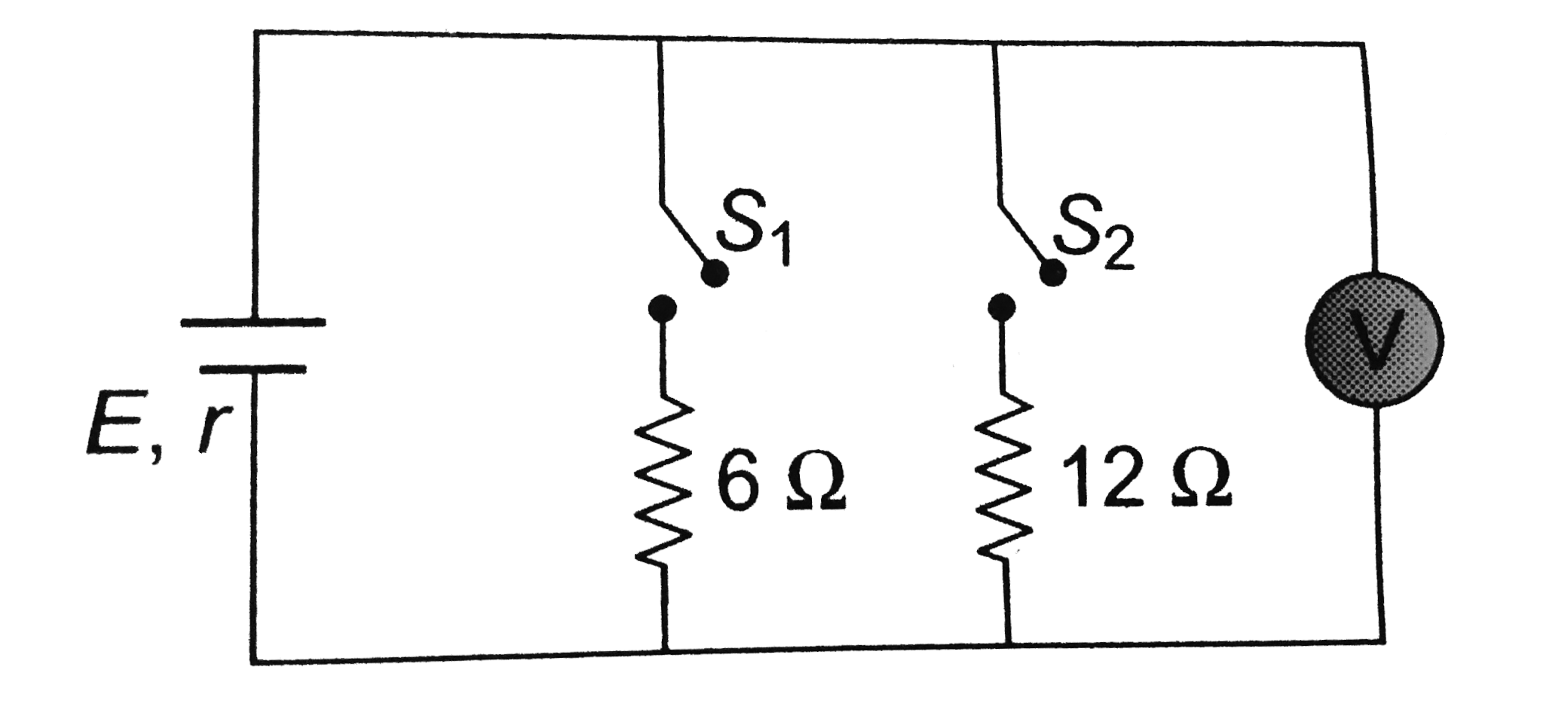
View SolutionIn the circuit shown, when switch S1 is closed and S2 is open, the ideal voltmeter shows a reaiding of 18V. When switch S2 is closed and S1 is open, the reading of voltmeter is 24V. When S1 and S2 both are closed, the voltmeter reading will be
View SolutionIn the given circuit , R1≠R2 and the reading of the voltmeter is the same, irrespective of whether the switch S is open or closed. Then, which of the following is correct?
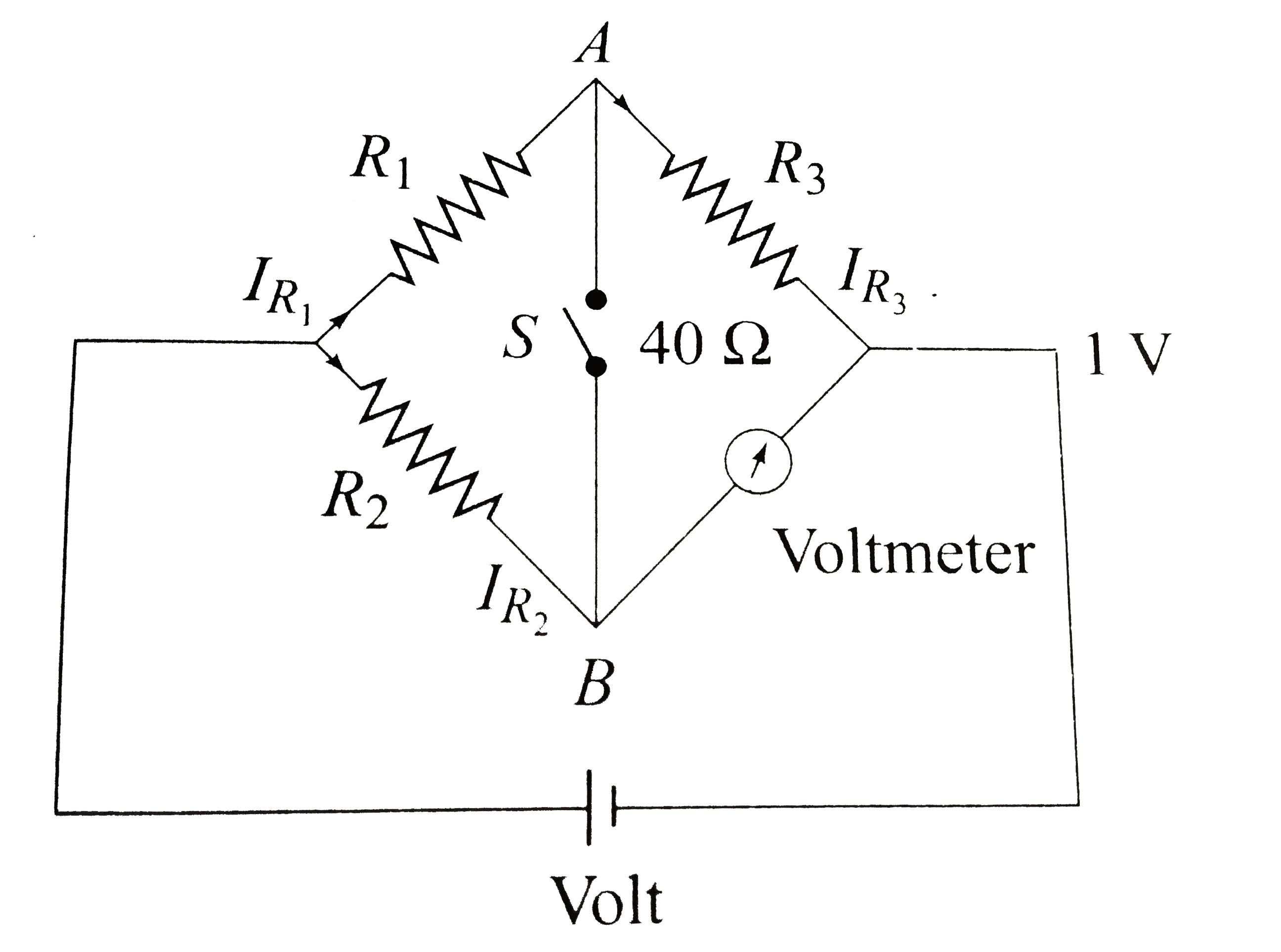
View SolutionThe ammeter A reads 2A and the voltmeter V reads 20V, the value of resistance R is (Assuming finite resistance's of ammeter and voltmeter)
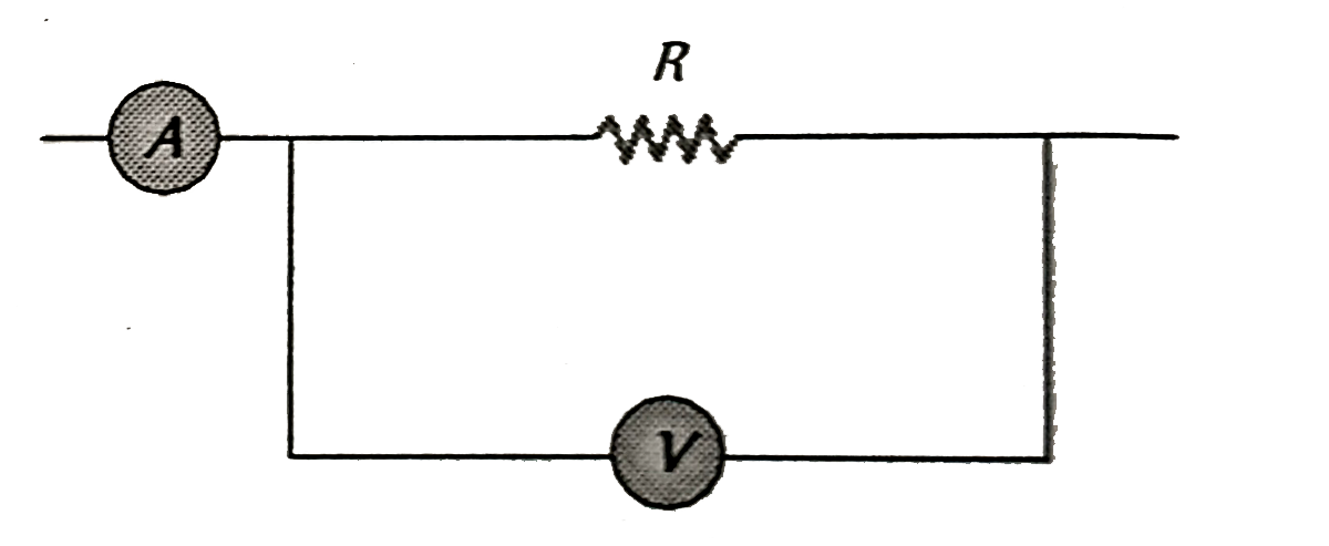
View SolutionLet V and I respresent, respectively, the readings of the voltmeter and ammetre shows in Fig. 6.34, and let RV and RV be their equivalent resistances. Because of the resistances of the meters, the resistnce R is not simply equal to V/I.
(a) When the circuit is connected as shows in Fig. 6.34 (a), shows that R=VI−RA
Explain why the true resistance R is always less than V/I.
(b) When the connections are as shows in Fig.6.34 (b)
Show that R=VI−(V/RV)
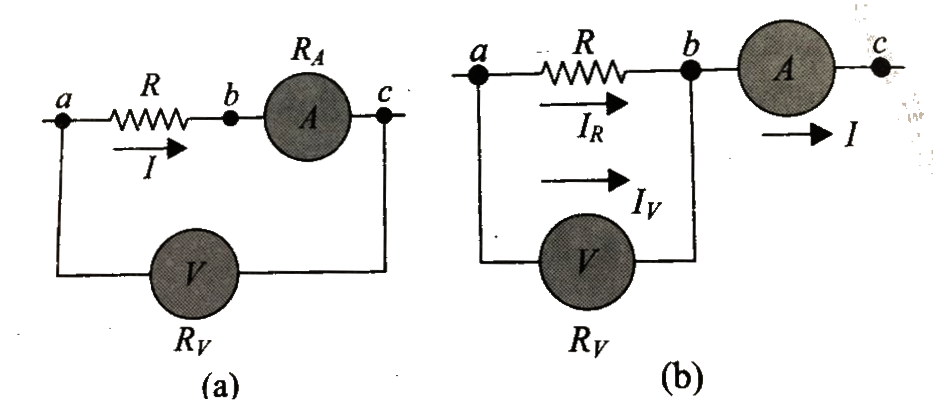
Explain why the true resistance R is always greater than V/I.
(c ) Show that the power delivered to the resistor in part
(i) is IV−I2RA and that in part (ii) is IV−(V2/RV)
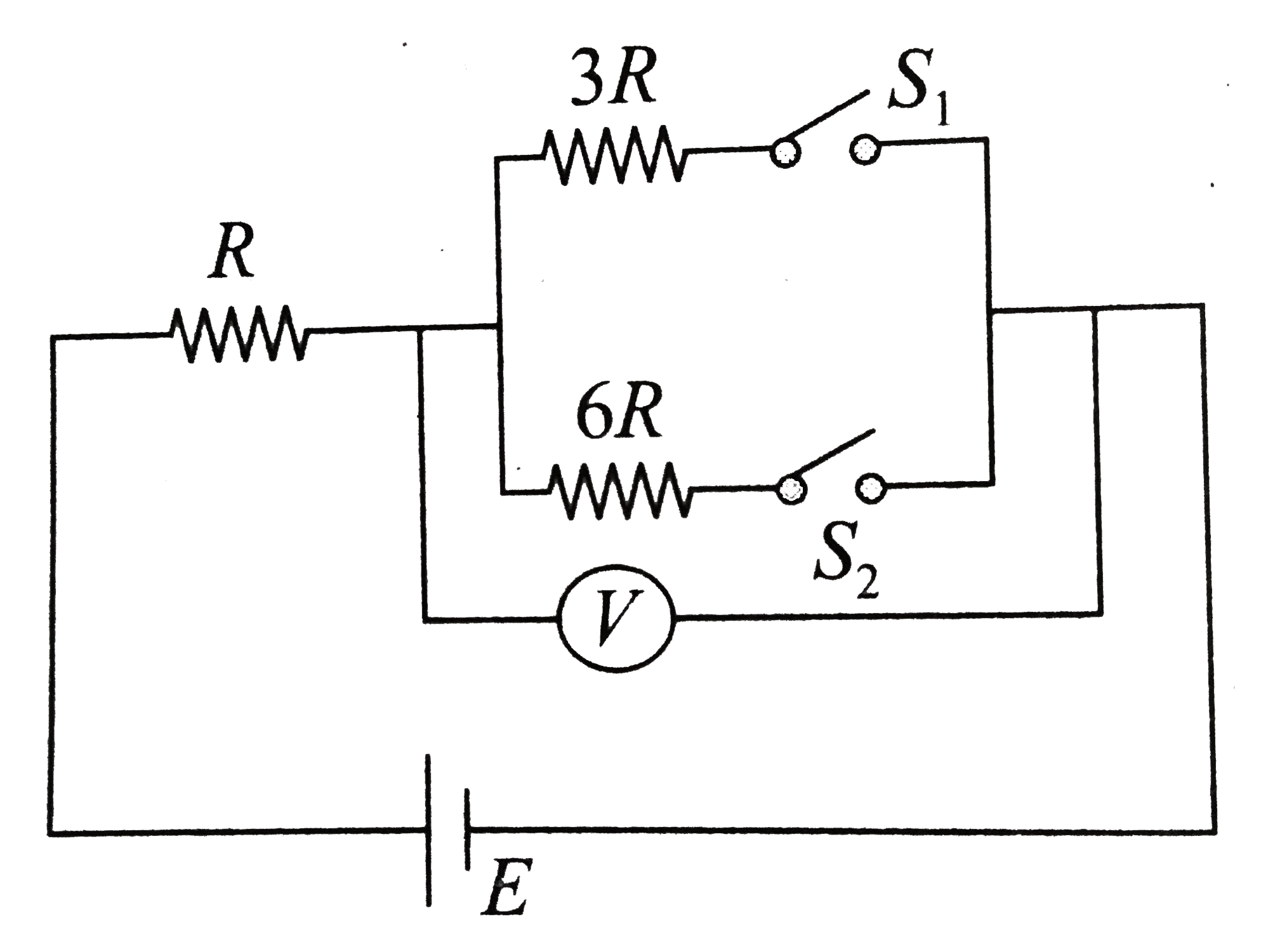
View SolutionIn the circuit shown in figure, reading of voltmeter is V1 when only S1 is closed, reading of voltmeter is V2 when only S2 is closed, and reading of voltmeter is V3 when both S1andS2 are closed. Then .
View SolutionA voltmeter of resistance 600Ω when connected in turn across resistances R1 and R2 gives readings of V1 and V2, respectively. If the battery is ideal, then
View SolutionIn the shown figures (1) and (2), capacitors are in steady state. Charging batteries are removed a switches S1 and S2 are closed at time t=0. The plot In I (I is the current in the resistor ) against time t the resitors R1 and R2 are shown in the figure. Choose the correct option (s)
(1)
View Solution
