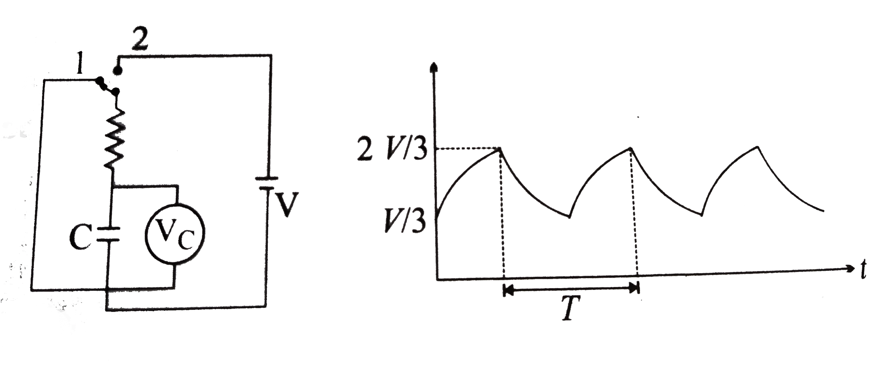
VC is the ideal voltmeter in the figure. Resistance of the resistor shown is R. Initially the switch is in position 2 when charging of the capacitor starts. Initially the capacitor was uncharged. The switch in circuit shifts automatically from 2 to 1 when VC>2V/3 and goes back to 2 from 1 when VC<V/3. The ideal voltmeter reads voltage across capacitor as plotted. What is the period T of the wave from in terms of R and C ?
 ,
,
3RC1n3
2RC1n2
(RC/2)1n2
none of these
The correct Answer is:B
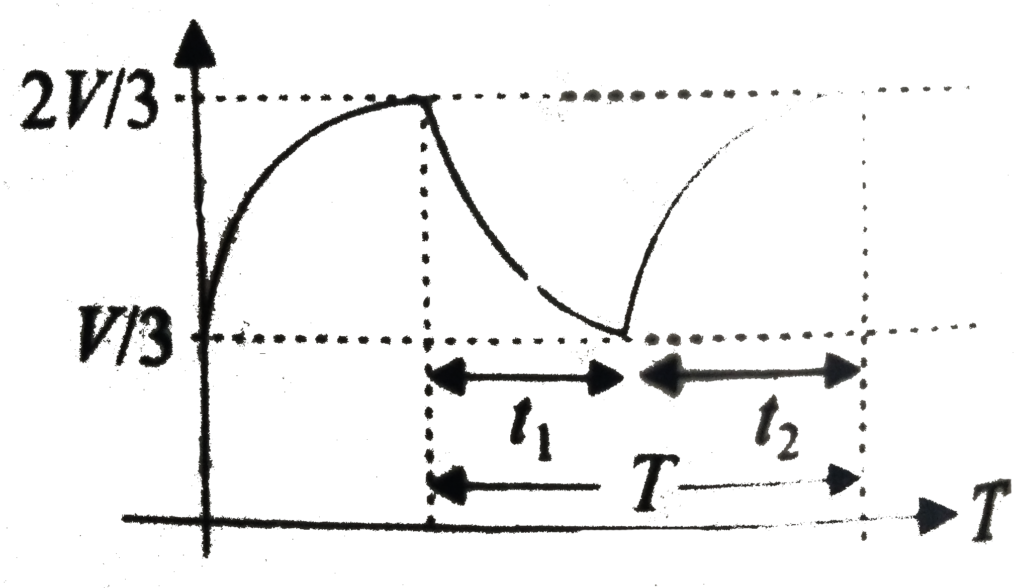
b. t1 is the time of capacitor to discharge from 2V/3 to V/3.
For this , V3=2V2e−t1/τ or t1=τ1n2=RC1n2
t2 is time for charging of capacitor
from V/3to2V/3.
So ∫2VC/3VC/3dqVC−q=∫t20dtRC
or t2=RC1n2
T=t1+t2=2RC1n2
 .
.
সম্পর্কিত প্রশ্ন
The switch in Figure (a) closes when Vc=2V/3 and opens when Vc=V/3. The voltmeter reads a voltage as plotted in figure (b). What is the period T of the waveform? (take R1=6R and R2=3R, and ln2=0.7 if required)
(a)
View SolutionCondsider
 .
.
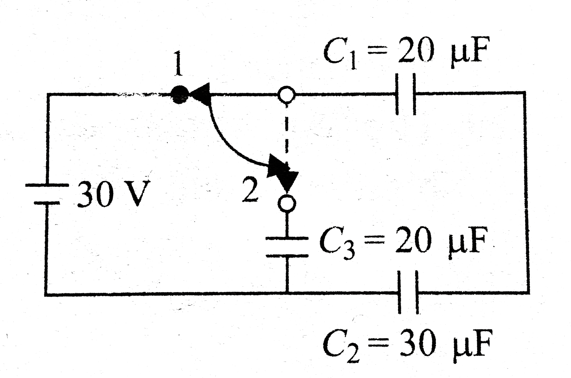
In the circuit shown is the switch can be shifted to positions 1 and 2 The charge on capacitor C1 when the switch is at position 1 is.
View SolutionIf the reading of the ideal voltmeter shown in the circuit is 2V the internal resistance of the two identical cells is
_2019_CBT5_E01_030_Q01.png)
View SolutionInitially, the switch is in position 1 for a long time. At t=0, the switch is Obtain expressions for VC and VR for t>0
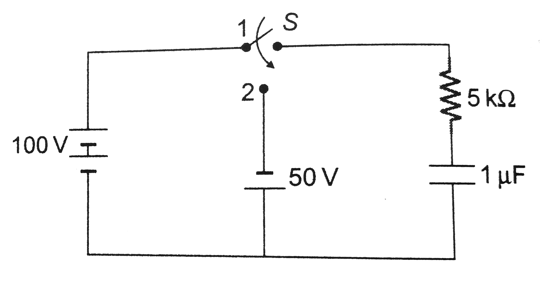
View SolutionThe capacitor C shown in the figure is in steady state condition when switch is shifted from position 1 to position 2.The heat liberated in the process is
_PHY_E05_272_Q01.png)
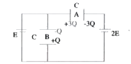
View SolutionThe initial charge across capacitors A and B are shown with Q=CE. Find the ratio of final charge in capacitor A to the final charge in capacitor B, when cells are switched on.
View SolutionIn the R-C circuit shown in the figure the total of 3.6×10⁻³J is dissipated in the 10 ohms resistor when the switch S is closed. The initial charge on the capacitor is

View SolutionPassage-III
In the circuit shown, the battery is ideal with emf V. The capacitor is initially uncharged. The switch is closed at time t = 0
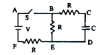
The current in the branch BE at t=∞ is
View SolutionPassage-III
In the circuit shown, the battery is ideal with emf V. The capacitor is initially uncharged. The switch is closed at time t = 0
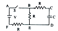
The current in branch containing capacitors at any time t is
View SolutionIn the given figure switch is open initially and capacitor C2 is unchanged
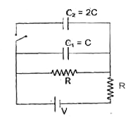
Charge on C2 just after closing the switch is
View Solution
