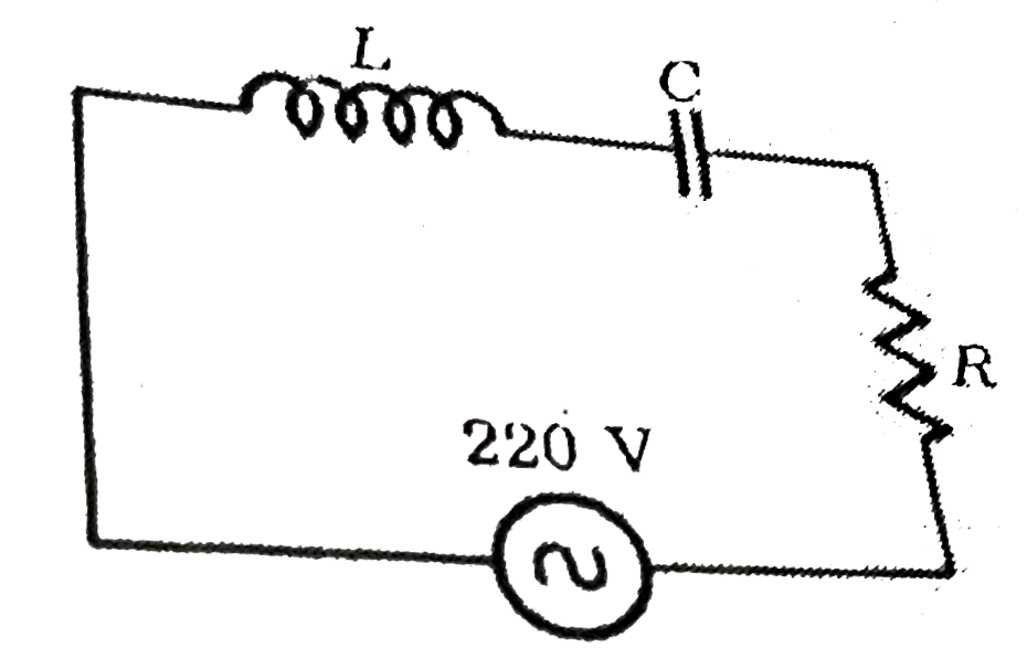
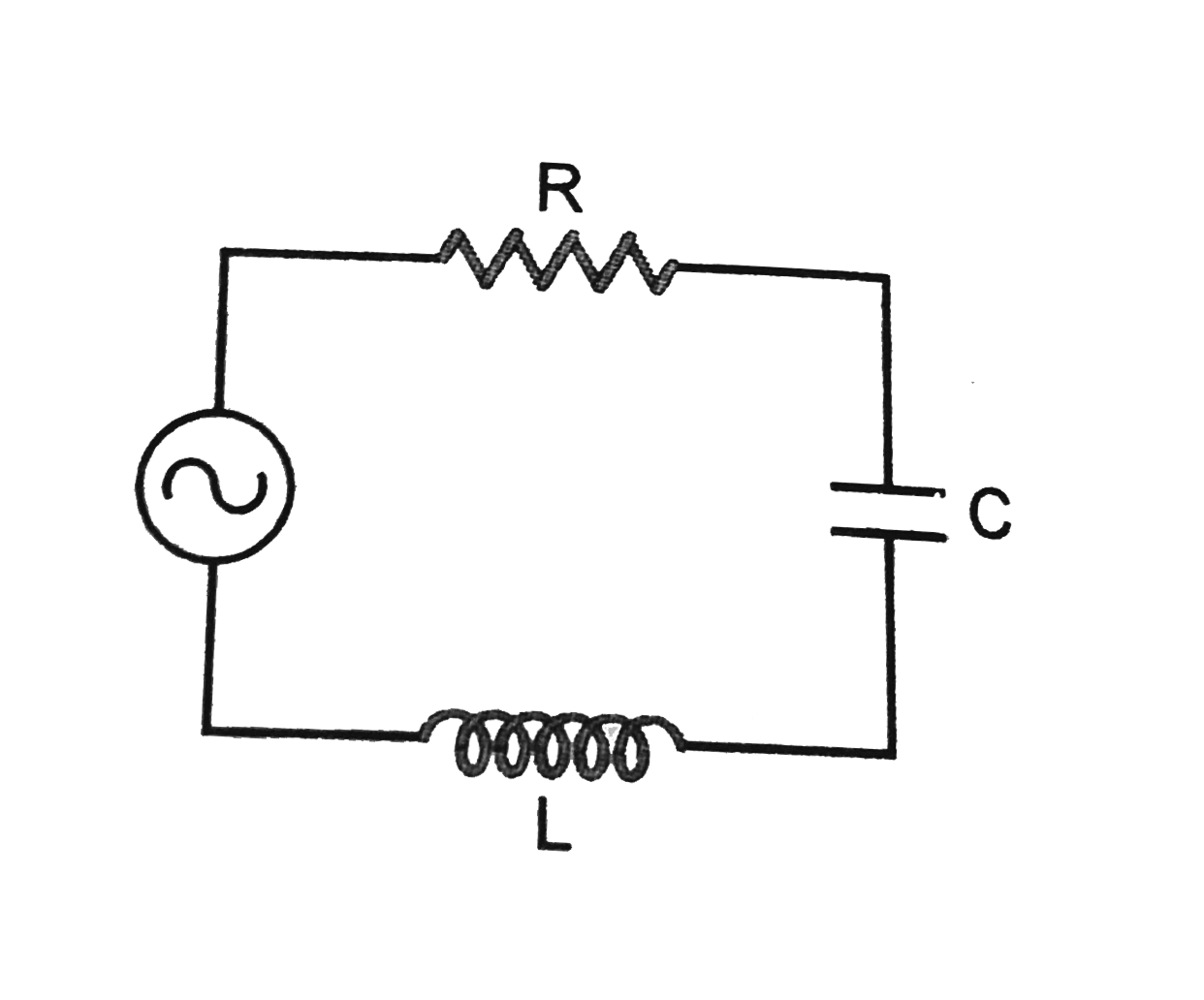
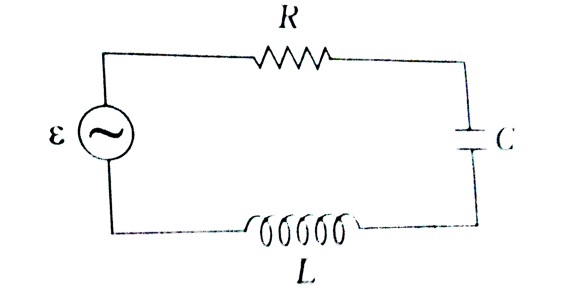
A 200 V varialbe frequency a.c. source is connected to a series combination the angular C=80μF and R=40Ω. Calculate the angular frequency of the soucre to get maximum current in the cicuit, the current amplitude at resonance and power dissipated in the circuit.
To solve the problem step by step, we will calculate the angular frequency at resonance, the current amplitude at resonance, and the power dissipated in the circuit.
Given Data:
- Voltage (V) = 200 V (RMS)
- Inductance (L) = 5 H
- Capacitance (C) = 80 μF = 80 × 10^(-6) F
- Resistance (R) = 40 Ω
Step 1: Calculate the Angular Frequency at Resonance (ω₀)
At resonance in an RLC circuit, the inductive reactance (X_L) equals the capacitive reactance (X_C). The formula for the resonant angular frequency (ω₀) is given by:
ω0=1√LC
Substituting the values of L and C:
ω0=1√5×80×10−6
Calculating the denominator:
LC=5×80×10−6=400×10−6=4×10⁻⁴
Now, taking the square root:
√4×10−4=0.02
Thus,
ω0=10.02=50rad/s
Step 2: Calculate the Current Amplitude at Resonance (I₀)
At resonance, the impedance (Z) of the circuit is equal to the resistance (R):
Z=R=40Ω
The current amplitude (I₀) can be calculated using Ohm’s law:
I0=VrmsZ
Substituting the values:
I0=20040=5A
Step 3: Calculate the Power Dissipated in the Circuit (P)
The power dissipated in the circuit can be calculated using the formula:
P=V2rmsR
Substituting the values:
P=200240=4000040=1000W
Summary of Results:
- Angular frequency at resonance (ω₀) = 50 rad/s
- Current amplitude at resonance (I₀) = 5 A
- Power dissipated in the circuit (P) = 1000 W
- Voltage (V) = 200 V (RMS)
- Inductance (L) = 5 H
- Capacitance (C) = 80 μF = 80 × 10^(-6) F
- Resistance (R) = 40 Ω
- Angular frequency at resonance (ω₀) = 50 rad/s
- Current amplitude at resonance (I₀) = 5 A
- Power dissipated in the circuit (P) = 1000 W
Similar Questions
A variable frequency 230 V alternating voltage source is connected across a series combination of L=5.0H,C=80μF and R=40Ω
(i) Calculate the angular frequency fo the source which drives the circuit in resonance.
(ii) Obtain r.m.s. the impedance of the circuit and amplitude of current at resonance frequency
(iii) Obtain r.m.s. potential drop across the three elements of the circuit at resonating frequency.
(iv) How do you explain the observation that the algerbraic sum of voltages across the three elements obtained is greater than the supplied voltage.
View SolutionAn AC source of rms voltage 220 V and variable frequency is connected across a series combination of 5 H inductance 80μF capacitance and 40Ω resistance . Calculate frequency which can drive the circuit to resonance. What will be the impedance of the circuit for this frequency and peak current ?
View Solution
Knowledge Check
A series LCR circuit is connected to an ac source of frequency v and a voltage V. At this frequency, reactance of the capacitor is 350 Ω while the resistance of the circuit is 180Ω . Current in the circuit leads the voltage by 54∘ and power dissipated in the circuit is 140 W. Then the voltage V is
A250VB260VC270VD280VA resistance R and an inductance L are connected in series in an a.c. circut. If ω is the angular frequency of the source, then the power factor is given by
AωLRBRωLCR√R2+ω2L2DR√R2−ω2L2
Fig 14.18 shows a series LCR circuit connected to a variable frequency 200 V source:
L=4.0H,C=100μF and R=40Ω.
(i) Calculate the resonant frequency of the circuit.
(ii) Obtain the impedance of the circuit and the amplitude of the current at resonating frequency.
(iii) Determine r.m.s. potential drop across L.

View SolutionAn inductor of 200 mH, capacitor of 400μF and a resistance of 10 ohm are connected in series to an a.c. source of 50 V of varialbe frequency. Calculate (i) angular frequency at which maximum power dissipation occurs in the circuit and the corresponding value of effective current, and (ii) value of Q factor is the circuit.
View SolutionA series LCR circuit connected to a variable frequency 230 V source has L = 5.0 H, C=80μF, R=40Ω, Fig.
(a) Determine the source frequency which drives the circuit in resonance.
(b) Obtain the impedance of the circuit and amplitude of current at at resonating frequency.
(c ) Determine the r.m.s. potential drops acorss the three elements the circuits. Show that the potential drop acorss the LC combination is zero at the resonating frequecny.

View SolutionA series LCR a.c. circuit has L = 2.0 H, C = 32 μF and R = 10 Ω.
(a) At what angular frequency of a.c. will it resonate ?
(b) Calculate the Q value of the circuit.
View Solution(a) Prove that an ideal capacitor in ac circuit does not dissipate power.
(b) An inductor of 200m H, capacitor of 400μf and a resistaor of 10Ω are connected in series to ac source of 50 V of variable frequency. Calculate the
(i) angular frquency at which maximum power dissiplation occurs in the circuit and the corresponding value of the effective current, and
(iii) value of Q-factor in the circuit.
View SolutionFigure here, shows a series L-C-R circuit connected to a variable frequency 230 V source. L = 5.0H, C = 80μF and r =40Ω
(a) Determine the source frequency which drives the circuit in resonance.
(b) Obtain the impedance of the circuit and the amplitude of current at the resonating frequency.
(c) Determine the rms potential drops across the three elements of the circuit. show that the potential drop across the L-C combination is zero at the resonating frequency.

View Solution

