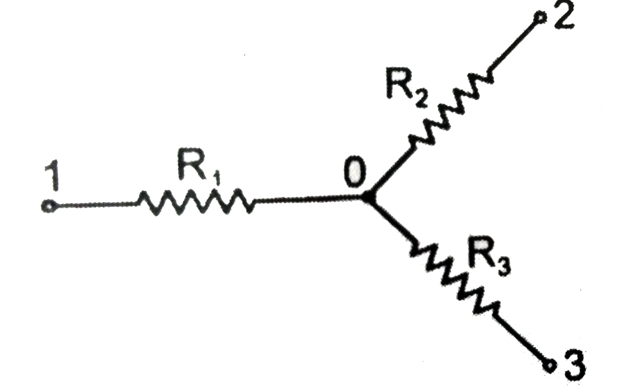
(i) Find the current flowing through the resistance R1 of the cirucit shown in figure if the resistacnes are equal to R1=10Ω,R2=20Ω and R3=30Ω, and the potentials of points 1, 2 and 3 are equal to φ1=10V,φ2=6V, and φ3=5V.
2 V
3 V
4 V
5 V
The correct Answer is:D
Step by step video solution for (i) Find the current flowing through the resistance R_(1) of the cirucit shown in figure if the resistacnes are equal to R_(1)=10Omega, R_(2)=20 Omega" and "R_(3)=30Omega, and the potentials of points 1, 2 and 3 are equal to varphi_(1)=10V, varphi_(2)=6V," and "varphi_(3)=5V. by Physics experts to help you in doubts & scoring excellent marks in Class 12 exams.
Updated on:21/07/2023Topper's Solved these Questions
- CURRENT ELECTRICITYBOOK - RESONANCE ENGLISHCHAPTER - CURRENT ELECTRICITYEXERCISE - Exercise-1 (Part-3)
2 Videos
- CURRENT ELECTRICITYBOOK - RESONANCE ENGLISHCHAPTER - CURRENT ELECTRICITYEXERCISE - Exercise-2 (Part-1)
24 Videos
- CURRENT ELECTRICITYBOOK - RESONANCE ENGLISHCHAPTER - CURRENT ELECTRICITYEXERCISE - Exercise-1 (Part-1)
41 Videos
- COMMUNICATION SYSTEMSBOOK - RESONANCE ENGLISHCHAPTER - COMMUNICATION SYSTEMSEXERCISE - Exercise 3
13 Videos
- DAILY PRACTICE PROBLEMBOOK - RESONANCE ENGLISHCHAPTER - DAILY PRACTICE PROBLEMEXERCISE - DPP.No.71
1 Video
Similar Questions
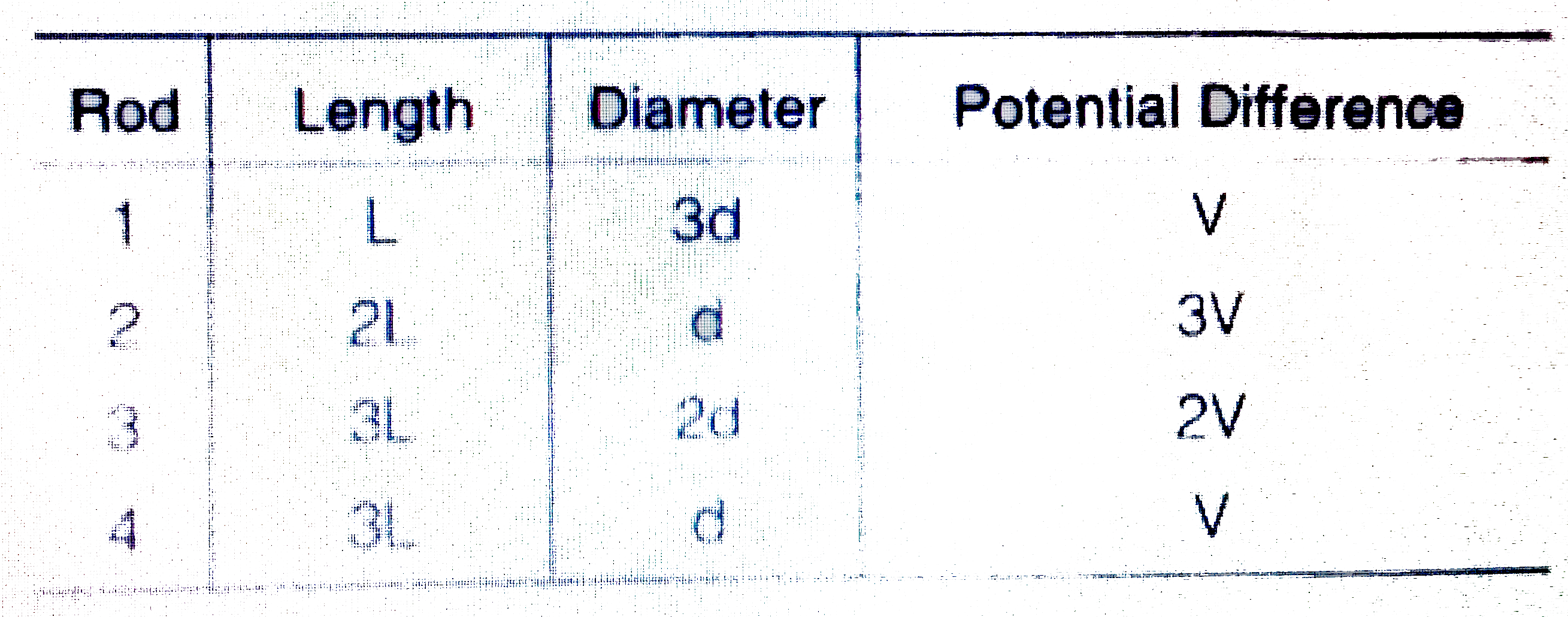
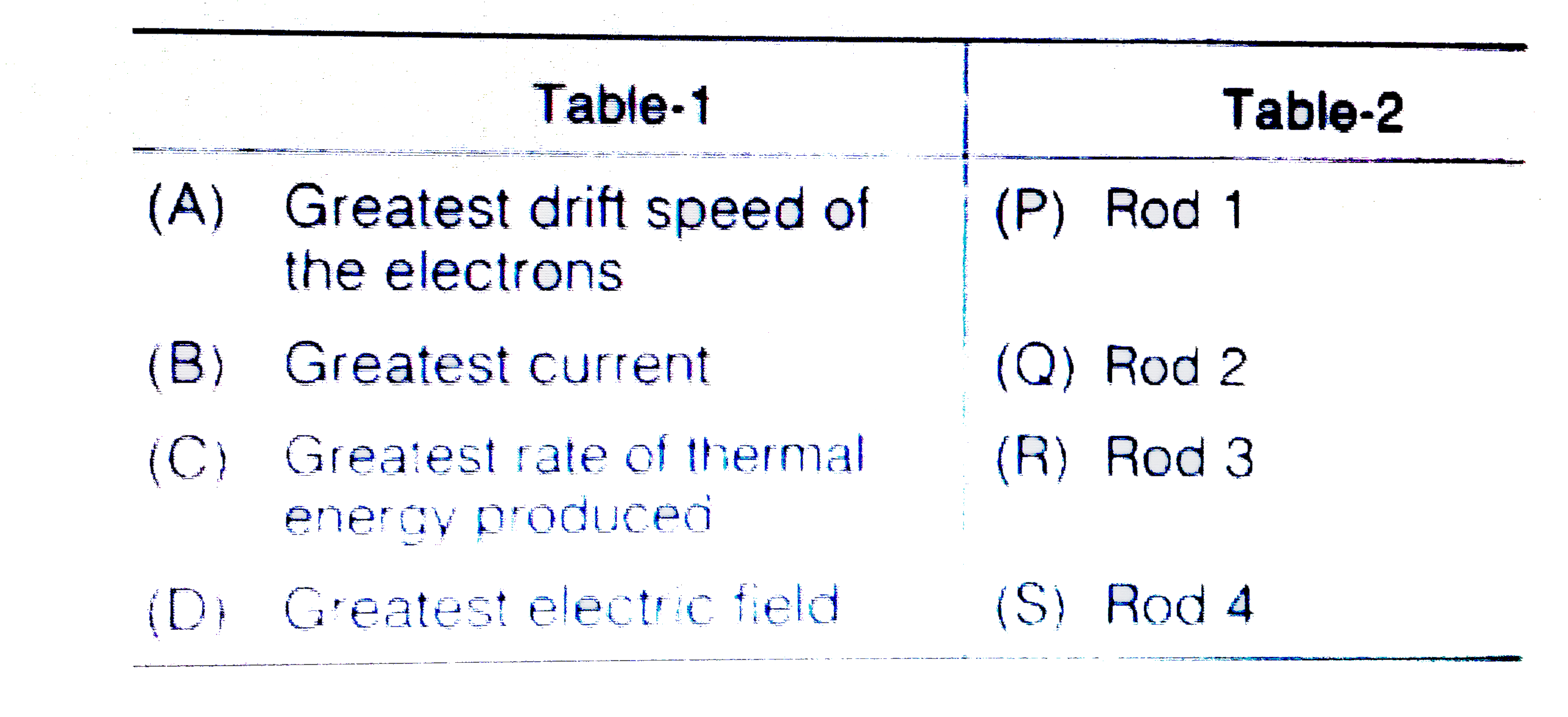
the following table gives the lengths of four copper rods at the temperature ,their diameters and the potential differences between their ends.
View SolutionIf a copper wire is stretched to make it 0.1% longer, then the percentage change in resistance is approximately -
View SolutionThe current through a wire depends on time as
I=i0+αt,
where i0=10Aandα=4As−1.Find the charge crossed through a section of the wire in 10 second
View SolutionConsider telecommunication through optical fibers. Which of the following statements is not true ?
View SolutionConsider a uniform wire of length l. Cross-sectional area A, Young's modulus of the material of the wave is Y. Some information related to the wire is given in column-1 and dependence of the result is given in column-2. Then match the approprite choice between the columns and match the list given in options
Column-I Column-II(A) Let us suspend wire vertically from a (p) Young'sModulusrigud support and attach a mass m atits lower end. If the mass is slightly pulleddown and released, it executes S.H.Mof a time period which will depend on(B) Work done in stretching the wire up to length (q) elongation (x)l+xwill depend on(C) If the given is fixed between two rigid (r) length (l)supports and its temperature is decreasedthermal stress that develops in the wirewill depend on(D) If the wire is pulled at its ends equal and (s) area of cross-section (A) opposite forces of magnitude F so that itundergoes an elongation x, according toHook's law, F=kx, where k is the forceconstant.Force constant (k) of the wirewill depend on
View SolutionFind a potentail difference varphi_(1) - varphi_(2) between points 1 and 2 of the circuit shown in Fig if R_(1) 1= 10 Omega, R_(2) = 20 Omega, E_(1) = 5.0 V , and E_(2) = 2.0 V . The internal resisances of the current sources are negligible.
View SolutionIn the circuit shown in Fig. the emf of the sources is equal to ξ=5.0V and the resistances are equal to R1=4.0Ω and R2=6.0Ω. The internal resistance of the source equals R=1.10Ω. Find the currents flowing through the resistances R1 and R2.

View SolutionIn the circuit shown in Fig, the sources have emf'sξ1=1.5V,ξ2=2.0V,ξ3=2.5V , and the resistances are equal to R1=10Ω,R2=20Ω,R3=30Ω. The internal resistances of the sources are negligible. Find : ltbrtgt (a) the current flowing thorugh teh resistance R1 ,
(b) a potential differences φA−φB between the points A and B between the points A and B.

View SolutionFind a potential difference varphi_(A) - varphi_(B) between the plates of a capacitor C in the circuit shown in Fig, if the sources have emf's E_(1) = 40 V, E_(2) = 1.0 V and the resistances are equal to R_(1) = 10 Omega, R_(2) = 20 Omega , and R_(3) = 30 Omega . The internal resistances of the sources are negligble.
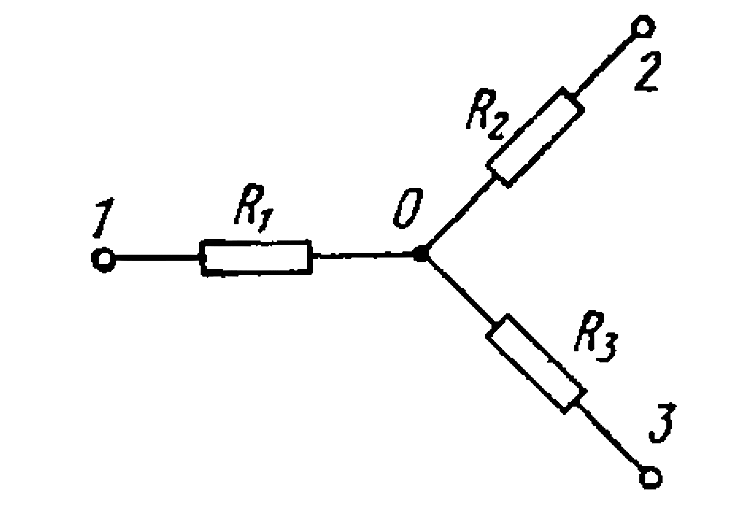
View SolutionFind the current flowing through the resistance R1 of the circuit shown in Fig. If the resistances are equal to R1=10Ω.R2=20Ω and R3=30Ω, and the potential of points 1,2 and 3 are equal to φ1=10V,φ2=6V, and φ3=5V
View SolutionIn the circuit shown in the figure R_(1) =3 Omega,R_(2) = 2 Omega and R_(3) = 5 Omega Emf of the cell epsilon = 6 Volt. (a) Infinitely many 1 Omega resistors are added in parallel to R_(1) and R_(2) . Find current through R_(2) and potential drop across it. (b) Infinitely many 1 Omega resistors are added in series to R_(3) . Find the potential drop across R_(3) and current through it.
View SolutionThe circuit is shown in the following figure. The potential at points A, B, C, D and O are given. The currents in the resistance R_(1), R_(2) and R_(3) are in the ratio of 4:2:1 . What is the ratio of resistance R_(1),R_(2),R_(3) and R_(4) ?
View SolutionFind the current flowing through the resistance R_(1) of the circuit shown in figure-3.103. the resistances are equal to R_(1)=10Omega,R_(2)=20Omega and R_(3)=30Omega and the potentials of points 1,2 and 3 are given as V_(1)=10V,V_(2)=6V and V_(3)=5V .
View SolutionFind the currents in the Y connection of 3 resistances R_(1) = 10Omega , R_(2)=20Omega and R_(3)= 30 Omega . When the terminals of R_(1) , R_(3) and R_(3) are maintained at potentials V_(1) = 10V, V_(2) =6V and V_(3) = 15V.
View SolutionThe potential difference in volt across the resistance R_(3) in the circuit shown in figure, is (R_(1)=15Omega,R_(2)=15Omega, R_(3)=30Omega, R_(4)=35Omega)
View Solutionदर्शाए गए परिपथ में R1=4Ω,R2=R3=5Ω,R4=10Ω तथा ε=6V परिपथ का तुल्य प्रतिरोध तथा प्रत्येक प्रतिरोधक में बहने वाली धारा के मान परिकलित कीजिए।
View Solution

