In the network shown, points A, B and C have potentials of 70 V, zero and 10V respectively
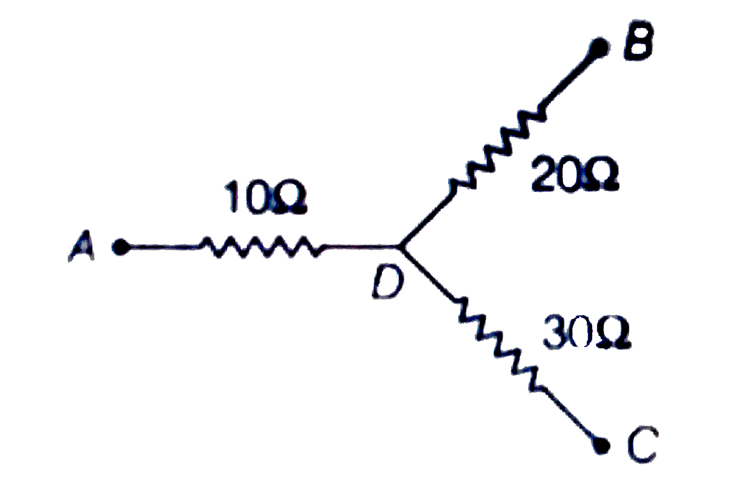
Point D is at a potential of 40 V
The currents in the sections AD, DB, DC are in the ratio 3:2:1
The currents in the sections AD, DB, DC are in the ratio 1:2:3
The network draws a total power of 200 W.
The correct Answer is:A, B, D
Step by step video solution for In the network shown, points A, B and C have potentials of 70 V, zero and 10V respectively by Physics experts to help you in doubts & scoring excellent marks in Class 12 exams.
Updated on:21/07/2023Topper's Solved these Questions
- CURRENT ELECTRICITYBOOK - RESONANCE ENGLISHCHAPTER - CURRENT ELECTRICITYEXERCISE - Exercise-2 (Part-4)
12 Videos
- CURRENT ELECTRICITYBOOK - RESONANCE ENGLISHCHAPTER - CURRENT ELECTRICITYEXERCISE - Exrcies-3(PART-1)
22 Videos
- CURRENT ELECTRICITYBOOK - RESONANCE ENGLISHCHAPTER - CURRENT ELECTRICITYEXERCISE - Exercise-2 (Part-2)
16 Videos
- COMMUNICATION SYSTEMSBOOK - RESONANCE ENGLISHCHAPTER - COMMUNICATION SYSTEMSEXERCISE - Exercise 3
13 Videos
- DAILY PRACTICE PROBLEMBOOK - RESONANCE ENGLISHCHAPTER - DAILY PRACTICE PROBLEMEXERCISE - DPP.No.71
1 Video
Similar Questions
In the circuit given in the figure, both batteries are ideal . Emf E1 of battery 1 has a fixed value, but emf E2 of battery 2 can be varied between 1.0Vand10.0V . The graph gives the currents through the two batteries as a function of E2 but are not marked as which plot corresponds to which battery. But for both plots, current is assumed to be negative when the direction of the current through the battery is opposite to the direction of that battery's emf (direction of emf is from negative to positive.)
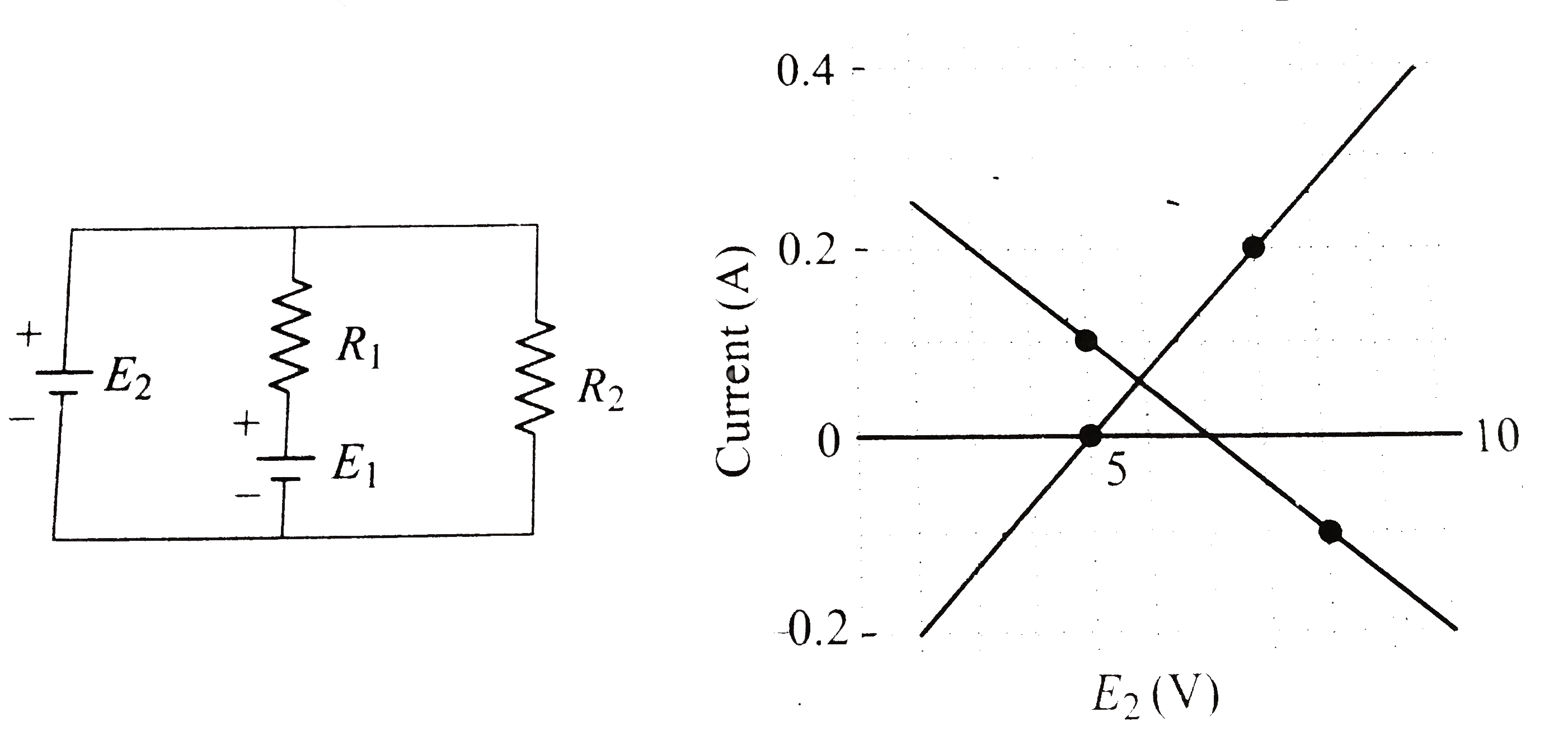
The value of emf E1 is
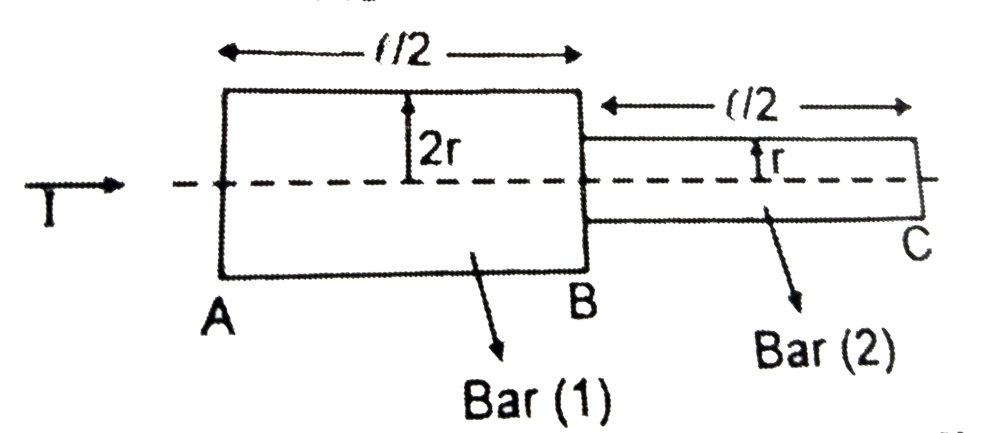
View SolutionTwo bars of equal resistivity ρ and radius 'r' and '2r' are kept in contact as show. An electric current is passed through the bars. Which one of the following is correct ?
View SolutionThe current density across a cylindrical conductor of radius R varies in magnitude according to the equation J=J0(1−rR) where r is the distance from the central axis. Thus, the current density is a maximum J0 at that axis (r=0) and decreases linearly to zero at the surface (r=R). Calculate the current in terms of J0 and the conductor's cross - sectional area A=πR2.
View SolutionConsider telecommunication through optical fibers. Which of the following statements is not true ?
View SolutionConsider a uniform wire of length l. Cross-sectional area A, Young's modulus of the material of the wave is Y. Some information related to the wire is given in column-1 and dependence of the result is given in column-2. Then match the approprite choice between the columns and match the list given in options
Column-I Column-II(A) Let us suspend wire vertically from a (p) Young'sModulusrigud support and attach a mass m atits lower end. If the mass is slightly pulleddown and released, it executes S.H.Mof a time period which will depend on(B) Work done in stretching the wire up to length (q) elongation (x)l+xwill depend on(C) If the given is fixed between two rigid (r) length (l)supports and its temperature is decreasedthermal stress that develops in the wirewill depend on(D) If the wire is pulled at its ends equal and (s) area of cross-section (A) opposite forces of magnitude F so that itundergoes an elongation x, according toHook's law, F=kx, where k is the forceconstant.Force constant (k) of the wirewill depend on
View SolutionIn the network shown in fig. , points A, B, and C are at potentials of 70 V, 0, and 10V, respectively.
View SolutionFind the potential difference between the points A and B for the network shown in Fig. 4.52.

View SolutionFor the network shown in figure, points A, B and C are at potentials of 70 V, zero and 10 V respectively
View SolutionIn the circuit given here, the points A,B and C are 70 V, zero, 10 V respectively . Then,
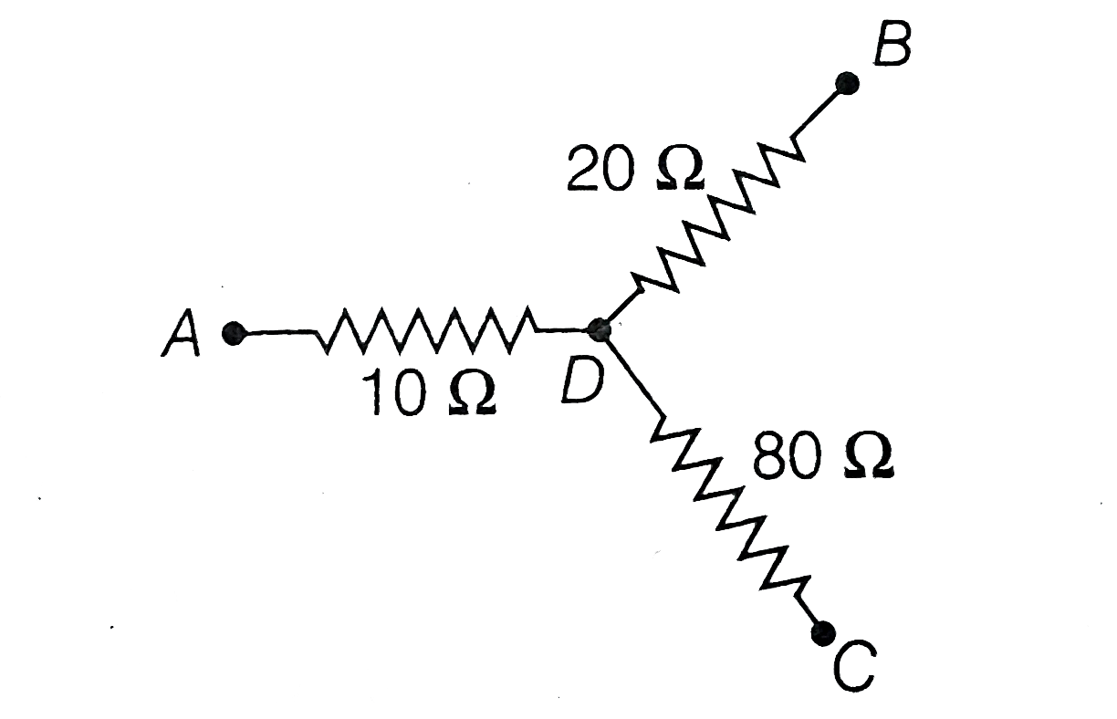
View SolutionAs shown in figure, if the point C is earthed and the point A is given a potential of 2000 V, then the potential at point B will be :
View SolutionIn the circuit diagram shown in Figure , the potentials of the points B, C and D are respectively -
View SolutionIn the circuit diagram shown in figure, the potentials of the points B, C and D are respectively.
View SolutionIn the circuit given here, the point A,B and C are 70 V, zero, 10 V respectively. Then
View SolutionIn the network shown A, B and C are at potentials of 70 V, zero V and 10 V respectively. The false one is 1) Point D is at a potential of 40 V 2) The currents in the sections AD, DB, DC are in the ratio 3:2:1 3) The current in the section AD, DB, DC are in the ratio 1:2:3 4) The network draws a total power of 200 W
View SolutionIn the circuit shown in the figure, if potential at point A is taken to be zero, the potential at point B is
View SolutionIn the circuit shown in the figure, if the potential at point A is taken to be zero, the potential at point B is
View Solution

