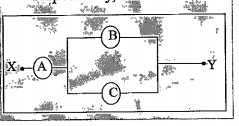
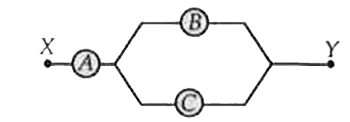
A,B and C are voltmetres of resistance R, 1.5R and 3R as shown in the figure. When some potential difference is applied between X and Y the voltmetre readings are VA,VB and VC respectively , Then:
 Solution in Tamil
VA≠VB=VC
VA=VB≠VC
VA≠VB≠VC
VA=VB=VC
Step by step video solution for A,B and C are voltmetres of resistance R, 1.5R and 3R as shown in the figure. When some potential difference is applied between X and Y the voltmetre readings are V_A,V_B and V_C respectively , Then: by Physics experts to help you in doubts & scoring excellent marks in Class 12 exams.
Updated on:21/07/2023Topper's Solved these Questions
Similar Questions
Nickel shows ferromagnetic property at room temperature. If the temperature is increased beryond Curie temperatue,then it will show
View SolutionThe work function of a surface of a photosensitive material 6.2eV . The wavelength of the incident radiation for which the stopping potentials is 5V lies in the:
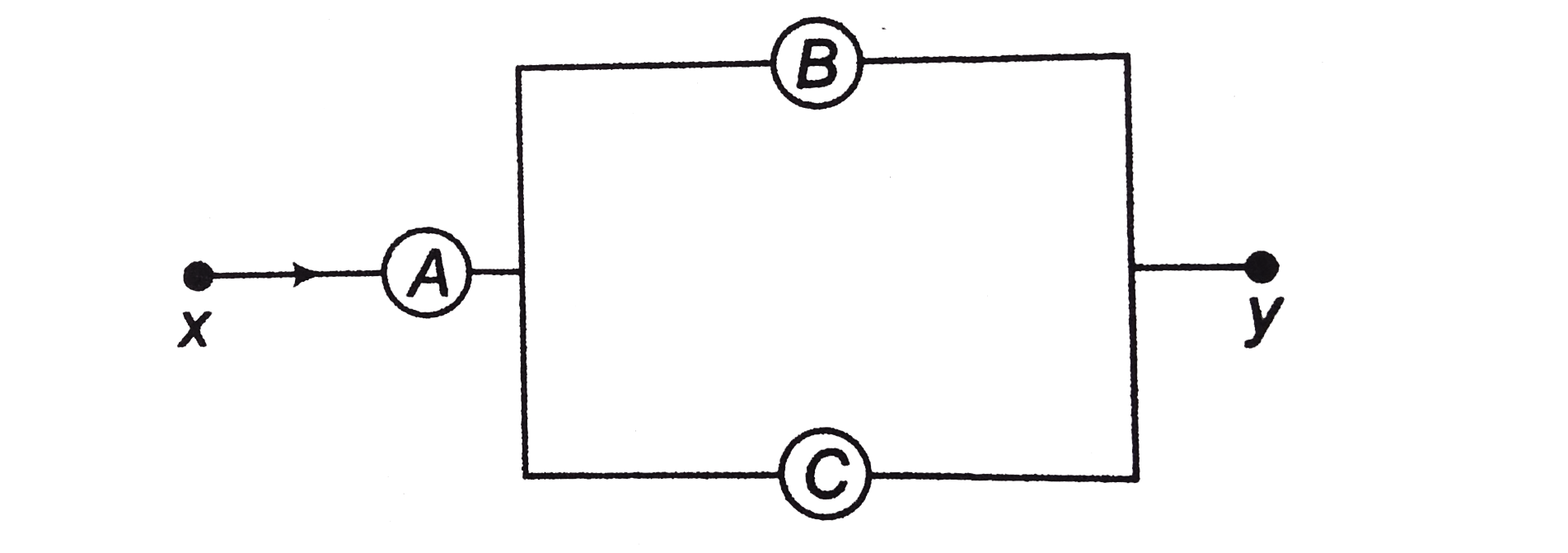
View SolutionA,B and C are voltmeters of resistances R,1.5R and 3R respectively. When some potential difference is applied between x and y the voltmeter readings are VA,V_BandV_C, then
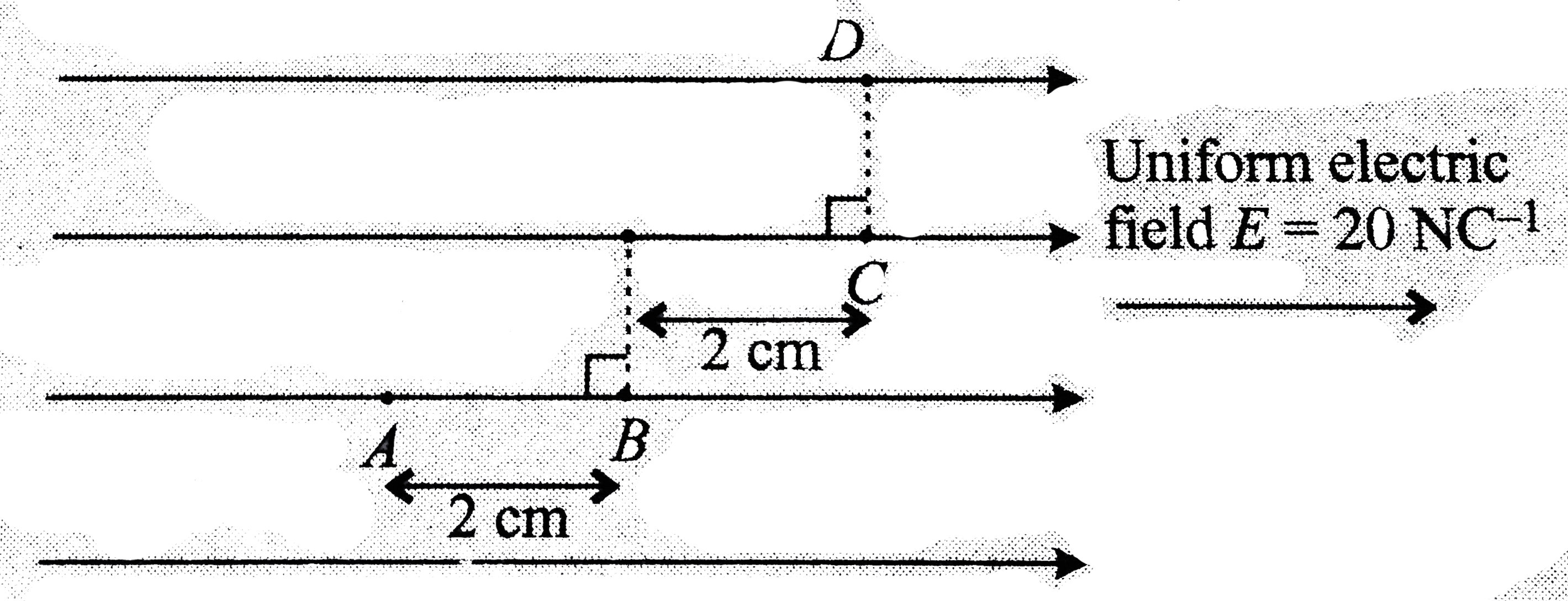
View SolutionFind out the following
a. VA−VB
b. VB−VC
c. VC−VA
d. VD−VC
e. VA−VD
f. Arrange the order of potential for points (A, B,C and D).
 .
.
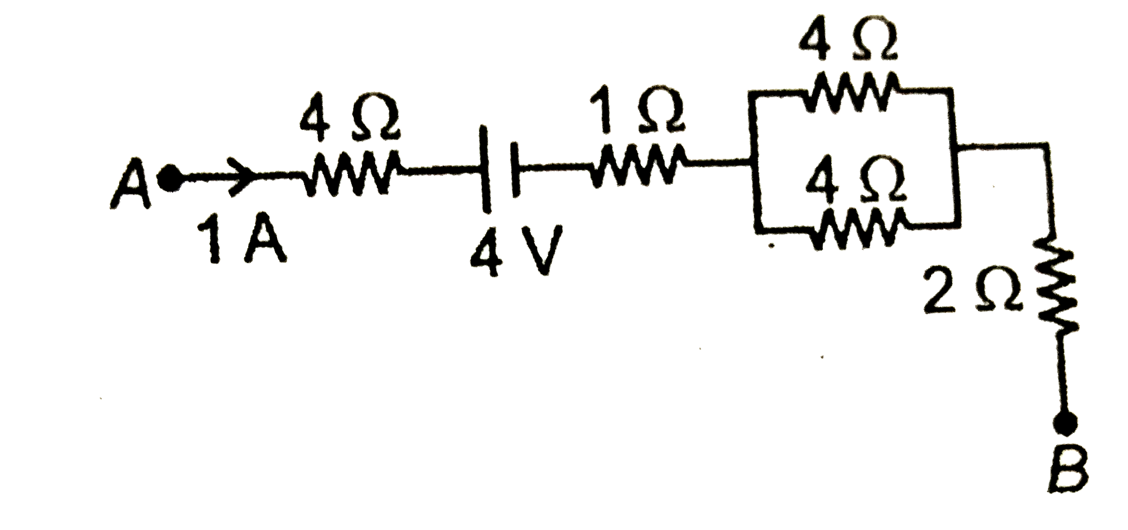
View SolutionThe potential difference (VA−VB) between the point A and B as shown in the figure is
View SolutionA,B and C are voltmeters of resistance R, 1.5 R and 3R respectively as shown in the figure. When some potential difference is applied between X and Y, the voltmeter reading are V_A , V_B and V_C respectively.
View SolutionA battery of e.m.f. 10 V is connected to resistances as shown in figure The potential difference V_A-V_B between the points A and B is
View SolutionThe voltmeters A,B, and C having resistance R, 1.5R and 3R respectively are used in a circuit as shown, When a P.D. is applied between X and Y, the reading of the voltmeters are V1,V2 and V3 respectively Then
View SolutionA, B and C arc voltmeters of resistance R, 1.5R and 3R respectively as shown in the figure. When some potential difference is applied between X and Y, the voltmeter readings are VA,VBandVC repsectively. Then :
View SolutionA,B and C are voltmeters of resistance R, 1.5 R and 3R respectively as shown in the fig. When some potential difference is applied between X and Y, the voltmeter reading are VA,VBandVC respectively.

View SolutionA, B and C are voltmeters of resistance R, 1.5R and 3R respectively as shown in the figure. When some potential difference is aaplied between X and Y, the voltmeter readings are VA,VB and VC respectively, then

View SolutionA, B and C are voltmeters of resistance R, 1.5R and 3R respectively as in fig. when some P.D. is applied between x and y, the voltmeter readings are V_A, V_B and V_C respectively, then:
View SolutionA,B and C are voltmeters of resistances R,1.5R and 3R respectively. When some potential difference is applied between x and y the voltmeter readings are VA,V_BandV_C, then

View SolutionA, B and C are voltmeters of resistances R, 1.5R and 3R respectively. When some potential difference is applied between x and y the voltmeter readings are V_A, V _B and V_C, then
View SolutionA, B and C are voltmeters of resistances R, 1.5R and 3R respectively. When some potential difference is applied between x and y the voltmeter readings are V_A, V _B and V_C, then
View SolutionA, B, C are three voltmeter of resistances 4000 Omega, 6000 Omega and 12000 Omega . When a potential difference is applied between X and Y, Voltmeter reading are V_A, V_B and V_C . Then
View Solution

