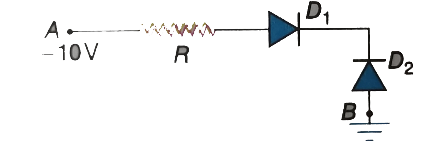
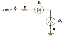
In a figure given alongside assuming the diodes to be ideal

D1 is forward biased and D2 is reverse biased and hence, current flows from A to B
D2 is forward biased and D1 is reverse biased and hence, no current flows from B to A and vice-versa
D1 and D2 are both forward biased and hence current flows from A to B
D1 and D2 are both reverse biased and hence no current flows from A to B and vice-versa
The correct Answer is:B
If Vp−Vn>0, then diode is in forward biased. In case of D1,Vp−Vn)=−10−0=−10<0, so D1 is in reverse biased and for D2, Vp−Vn=0−(−10)=10>0, So D2 is in forward biased.
Topper's Solved these Questions
- SEMICONDUCTOR DEVICES AND LOGIC GATESBook:BITSAT GUIDEChapter:SEMICONDUCTOR DEVICES AND LOGIC GATESExercise:BITSAT Archives
Explore 5 Videos
- RAY OPTICSBook:BITSAT GUIDEChapter:RAY OPTICSExercise:All Questions
Explore 39 Videos
- SOLVED PAPER 2017 Book:BITSAT GUIDEChapter:SOLVED PAPER 2017 Exercise:(PART -I) PHYSICS
Explore 40 Videos
Similar Questions
The circuit is equivalent to

View SolutionTwo plane mirrors each 1.6 m long, are facing each other. The distance between the mirrors is
20 cm. A light incident on one end of one of the mirrors at an angle of incidence of 30∘. How many times is the ray reflected before it reaches the other end?
View SolutionIf temperature of black body increases from 300K to 900K, then the rate of energy radiation increases by
View SolutionIn figure , assuming the diodes to be ideal ,
View SolutionAssuming that the junction diode is ideal the current through the diode is :-
View SolutionAssuming that the junction diode is ideal, the current in arrangement shown in figure is
View SolutionAssuming that the function diode is ideal, the current in the arrangement shown in figure is .
View SolutionAssuming that the junction diode is ideal, the current in arrangement shown in figure is

View SolutionFour silicon diodes are connected as shown in the figure. Assuming the diodes to be ideal. The current through the resistor R is
View SolutionIn Fig 1.50 assuming the diodes to be ideal

View SolutionIn Fig assuming the diodes to be ideal :

View SolutionIn figure, assuming the diodes to be ideal,
View SolutionAssuming the ideal diode, draw the output waveform for the circuit given in figure. Explain the waveform.
View SolutionIn figure , assuming the diodes to be ideal ,
View SolutionIn figure , assuming the diodes to be ideal ,
View Solution
